It was for 16F72 at 4Mhz written in cc5x. LCD is connected to PORTB.RS at RB7,RW at RB1,EN at RB6. DB7 at RB2,DB6 at RB3, DB5 at RB4, and DB4 at RB5. A function delay_ms() is used , which is not shown here.
code will work for 2x16 character LCD modules.
void lcdw(unsigned char m)
{
PORTB.2=m.7;
PORTB.3=m.6;
PORTB.4=m.5;
PORTB.5=m.4;
en=1;
nop();
nop();
en=0;
}
void nbw(unsigned char m)
{
PORTB.2=m.7;
PORTB.3=m.6;
PORTB.4=m.5;
PORTB.5=m.4;
en=1;
nop();
nop();
en=0;
PORTB.2=m.3;
PORTB.3=m.2;
PORTB.4=m.1;
PORTB.5=m.0;
en=1;
nop();
nop();
en=0;
}
void goadr(unsigned char a)
{
rs=0;
nbw(0x80 + a);
delay_ms(5); // delay of 5msec
}
void main()
{
................
TRISB=0;
PORTB=0;
rw=0;
rs=0;
lcdw(0x28); // lcdw function is only used once to initialise the LCD to 4 bit mode.
delay_ms(5);
nbw(0x28);
delay_ms(5);
nbw(0x0c);
delay_ms(5);
nbw(0x06);
delay_ms(5);
nbw(0x01);
delay_ms(5);
goadr(0x02);
rs=1;
nbw('a'); //displays the character "a" at location 0x02
nbw('b'); //displays the character "b" at location 0x03
.........................
}
Showing posts with label pic. Show all posts
Showing posts with label pic. Show all posts
Jan 10, 2010
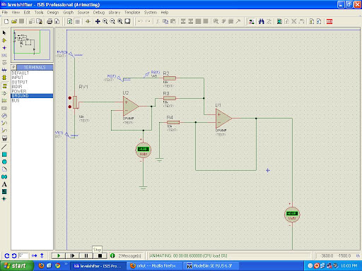
How to measure + and - 5 Volts using PIC microcontroller PIC1F4550
This post will explain you how to measure postitive and Negative 5 voltage using PIC microcontroller PIC1F4550
First config the ADC channel in your controller and in the ADCON Registers you have an option to select +Vref & -Vref values. say ADC is 10bit resolution i.e. 2^10 you will get max count from 0 to 1024. so the count "0" indicates your -Vref (-5v) value, count "512" indicates the 0V and the Max count 1024 indicates your +Vref (+5v).
so that is how you can calculate the Voltage
But there is the porblem with the Above approch as we cannot use -ve voltage greater that -0.3 with pic microcontroller which will permanently damage the PIC so first convert this range to 0 to 5 by some analog circuitry and then use it.
Here is the Circut for converting -5 - +5 to 0 - +5 voltage level.

Jul 23, 2008
Interfacing stepper motor with pic microcontrollers
Here I am not going to discuss completely about how to interface the stepper motor to the pic microcontrollers but will be talking about the what IC is to be used for interfacing the stepper motor to the pic microcontrollers
Also, the inductive windings will create a back EMF when the winding is turned off, this large current will also damage the PIC. The ULN 2003 is a "Driver" IC which simply accepts a logic state from the PIC and routes the necessary amount of current to the stepper windings. It also prevents the winding back EMF from affecting the PIC, in a sense isolating the pic from the large inductive load of the SM winding.
I'm not saying ULN is the best solution, it's a possibility. there are drivers available specifically for stepper motor control. You can control direction as well as control if the movement will be a full-step or half-step.
You might be also interested in:
:: assembly program to find out the largest number from an unordered array
:: Program to find out the number of even and odd numbers from a given series
:: assembly Program to create , write and close file
ULN2003
There are plenty of stepper motor drivers out there in the market. All you need to do is run a google search or ask around. The problem is that the PIC MicroC can not sink or source more than 25mA of current if I remember correctly. Whereas your stepper motor windings would draw a lot more current.Also, the inductive windings will create a back EMF when the winding is turned off, this large current will also damage the PIC. The ULN 2003 is a "Driver" IC which simply accepts a logic state from the PIC and routes the necessary amount of current to the stepper windings. It also prevents the winding back EMF from affecting the PIC, in a sense isolating the pic from the large inductive load of the SM winding.
I'm not saying ULN is the best solution, it's a possibility. there are drivers available specifically for stepper motor control. You can control direction as well as control if the movement will be a full-step or half-step.
You might be also interested in:
:: assembly program to find out the largest number from an unordered array
:: Program to find out the number of even and odd numbers from a given series
:: assembly Program to create , write and close file
Jul 20, 2008
speed control of DC motor using pic microcontroller
this is the program for speed control of DC motor using 89c51 microcontroller
code !
code !
$mod51
;***************************************
;* LED PWM 2 *
;* Amateur World *
;***************************************
; R7 is used to hold a value between 0 and 255 which will correspond to a
brightness
; level for the LED. Timer 0 will be used to create the Pulse Width Modulated
output.
; Timers are generally used to repeatedly measure the same fixed interval of
time.
; In this case we want to measure 2 periods of time. The high output period and
the
; low output period.
;***************************************
; RESET ;reset routine
ORG 0H ;locate routine at 00H
AJMP START ;jump to START
;***************************************
; INTERRUPTS (not used) ;place interrupt routines at appropriate
;memory locations
ORG 03H ;external interrupt 0
RETI
ORG 0BH ;timer 0 interrupt
AJMP TIMER_0_INTERRUPT ; go to interrupt routine (can be anywhere we want)
; since a jump does not return to this point we do not
; need a Return command
ORG 13H ;external interrupt 1
RETI
ORG 1BH ;timer 1 interrupt
RETI
ORG 23H ;serial port interrupt
RETI
ORG 25H ;locate beginning of rest of program
;***************************************
INITIALIZE: ; set up control registers
MOV TMOD,#00H ; set timer 0 to Mode 0 (8 bit Timer with 5 bit prescalar)
SETB TR0 ; turn on timer 0
MOV PSW,#00H
SETB EA ; Enable Interrupts (each individual interrupt must also be enabled)
SETB ET0 ; Enable Timer 0 Interrupt
RET
;***************************************
; Real code starts below.
;***************************************
; The LED is off during the high section and on during the low section of each
cycle
; The Flag F0 is used to remember whether we are timing tlow or thigh.
TIMER_0_INTERRUPT:
JB F0, HIGH_DONE ; If F0 is set then we just finished the high section of the
LOW_DONE: ; cycle so Jump to HIGH_DONE
SETB F0 ; Make F0=1 to indicate start of high section
SETB P1.0 ; Turn off LED
MOV TH0, R7 ; Load high byte of timer with R7 (our pulse width control value)
CLR TF0 ; Clear the Timer 0 interrupt flag
RETI ; Return from Interrupt to where the program came from
HIGH_DONE:
CLR F0 ; Make F0=0 to indicate start of low section
CLR P1.0 ; Turn on LED
MOV A, #0FFH ; Move FFH (255) to A
CLR C ; Clear C (the carry bit) so it does not affect the subtraction
SUBB A, R7 ; Subtract R7 from A. A = 255 - R7.
MOV TH0, A ; so the value loaded into TH0 + R7 = 255
CLR TF0 ; Clear the Timer 0 interrupt flag
RETI ; Return from Interrupt to where the program came from
;***************************************
START: ;main program (on power up, program starts at this point)
ACALL INITIALIZE ;set up control registers
MOV R7, #00H ; set pulse width control to dim
TEST: LCALL TIMER
INC R7 ;FROM HERE TO TEST IS THE TRICK TO VARY R7 AS WELL AS
;THE INTENSITY OF LED
CJNE R7,#0FFH,TEST
TEST1
TEST1: LCALL TIMER
DEC R7
CJNE R7,#00H,TEST1
LCALL TEST
;go to LOOP(always jump back to point labeled LOOP)
TIMER: push 00h
push 01h
push 02h ;store the internal location 00h,01h,02h contents
mov 02h,#03h
USER_L2:
mov 01h,#0ffh
USER_L1:
mov 00h,#0ffh
DJNZ 00h,$;decreament the internal location 00h
;content repeat until it becomes 0
DJNZ 01h,USER_L1 ;""""""
DJNZ 02h,USER_L2 ;""""""
pop 02h
pop 01h
pop 00h
RET
END ;end program
You might be also interested in:
:: Traffic light control system using 8086
:: Assembly Language Program to serve NMI
:: Interfacing Stepper Motor to 8086 using 8255
Jul 18, 2008
Edge triggeringin PIC16F877A
i am using the following program for edge triggering. i am using PIC16f877a Controller.
i put one key for the external interrupt.And using RB0/INT pin for the edge triggering concept.and i connected one led on porta to see the output.
i am using the HITECH c compiler
if cant able to bring the no of counts in LCD display.and led is blinking then do the following
for the lcd line initialization (0x38) takes more time , so that it would be better to pass 0x38 three times. i had only checked that much and also increase the delay time
You might be also interested in:
:: Traffic light control system using 8086
:: Assembly Language Program to serve NMI
:: Interfacing Stepper Motor to 8086 using 8255
i put one key for the external interrupt.And using RB0/INT pin for the edge triggering concept.and i connected one led on porta to see the output.
i am using the HITECH c compiler
#include<pic.h>
#include<stdio.h>
#define ldata PORTD
#define RS RC4
#define RW RC5
#define EN RC6
unsigned int d;
void Init_Int(void);
void cmd(unsigned char);
void cardiac_lcd(unsigned int);
void Msdelay(unsigned int);
void convert_disp(unsigned char);
void Msdelay(unsigned int time)
{
unsigned int i,j;
for(i=0;i<time;i++)
for(j=0;j<1275;j++);
}
void Lcd_disp()
{
cmd(0x38);
Msdelay(5);
cmd(0x0e);
Msdelay(5);
cmd(0x01);
Msdelay(5);
cmd(0x80);
Msdelay(5);
}
void cardiac_lcd(unsigned int value1)
{
ldata=value1;
RS=1;
RW=0;
EN=1;
Msdelay(1);
EN=0;
}
void cmd(unsigned char value)
{
ldata=value;
RS=0;
RW=0;
EN=1;
Msdelay(1);
EN=0;
// return;
}
void convert_disp(unsigned char val)
{
unsigned int b,c;
b=val/10;
c=val%10;
d=b|0x30;
}
void Init_Int()
{
RP0=1;
INTEDG=1;
// RPBU=1;
RP0=0;
GIE=1;
INTE=1;
}
void interrupt intr_tc()
{
unsigned int a=0;
if(INTF==1)
a=a++;
// if(a>10)
{
// convert_disp(a);
RA1=1;
}
INTF=0;
}
void main()
{
PORTA=0x00;
TRISA=0x00;
PORTB=0x00;
TRISB=0xff;
PORTC=0x00;
TRISC=0x00;
PORTD=0x00;
TRISD=0x00;
Lcd_disp();
Init_Int();
cardiac_lcd(d);
while(1)
{
//cardiac_lcd(d);
//RA1=0;
}
}
if cant able to bring the no of counts in LCD display.and led is blinking then do the following
for the lcd line initialization (0x38) takes more time , so that it would be better to pass 0x38 three times. i had only checked that much and also increase the delay time
You might be also interested in:
:: Traffic light control system using 8086
:: Assembly Language Program to serve NMI
:: Interfacing Stepper Motor to 8086 using 8255
Jul 14, 2008
8051, FREESCALE, PIC, AVR. which is better ?
I am presently working on developing applications using 8051 and freescale 8 bit microcontrollers.
I wanted to know. in what terms terms the 8-bit series of microncontrollers namely. 8051, PIC, FREESCALE, AVR. are better from each other and why?Actually now I have to learn PIC for the rest of the projects that i have two accomplish.
rishi says:
8051 ---- for learning n getting started in embedded systems
PIC ---- reach peripheral set and tremendous resources at every level
AVR ---- user friendly mainly for hobbyist
freescale ---- used in industry.
see PIC,AVR, FREESCALE all are used equally.the difference lies just in the application where they are used.
8051 is not used in industry.its modern derivative are used where they r almost equivalent 2 pic n avr in features like u can check high performance 8051 from silicon labs.i use them n they r monsters really.
anudeep says :
it isnt like that. many products till this date use 8051
example
(1)the coin box phones use atmel's 8052 at89c52 series. at least the 1se used
in india
(2)many mp3 players use 8051. where quality isnt an issue ie fr industrial purposes.if u want quality go fr vs2001(arm7 core)
(3)8051 is still used in card readers(sd,mmc and stuff----yes....there are ranges
from atmel)
(4)8051 is used fr protocol convectors ie usb to serial convectors,etc.
so it depends on the application frankly.
pic,avr,arm are equally important. cause at the end of the day.when you design a product the 2 most important things in your mind should be cost and quality.
so we have to choose the controllers accordingly.
You might be also interested in:
:: Assembly Language Programs on strings
:: Assembly Language Programs to compute an expression
:: Interfacing Analog-to-Digital converter to 8086 using 8255
Three phase latching relay programming for pic microcontroller 16f873a
I m using pic16f873a microcontroller and ICD2 Debugger cum programmer
I will give you brief introduction about my application.I need to toggle the relay on and off continuously.During on condition i need to check the continuity of relay contacts.For that i gave +5v supply to the relay contacts.output of this contact is given to microcontroller 25th pin.If the relay contact is working i will increase the relay test count and this count should written into the EEPROM.I f relay contact is not working micrcontroller should wait until the contact works.
TEST BSF PORTB,2 ;Set Turn off Relay
CALL DELAY
BCF PORTB,2 ;Clear Turn off Rly
CALL DELAY
CALL DELAY
CALL DELAY
CLRF PORTB
BSF PORTB,1 ;Set Turn on Rly
CALL DELAY
BCF PORTB,1 ;Clear Turn on Rly
CALL DELAY
CALL DELAY
CALL DELAY
MOVF PORTB,W
MOVWF CTAT_STATUS
BTFSS CTAT_STATUS,4
GOTO $-3
MOVLW 01H
MOVWF DATA_EE_ADDR
CALL READ
MOVWF DATA_TCNTL
MOVLW 00H
MOVWF DATA_EE_ADDR
CALL READ
MOVWF DATA_TCNTH
INCFSZ DATA_TCNTL,1
GOTO STORE
INCFSZ DATA_TCNTH,1
GOTO STORE
STORE MOVF DATA_TCNTL,W
MOVWF DATA_EE_DATA
MOVLW 01H
MOVWF DATA_EE_ADDR
CALL WRITE
MOVF DATA_TCNTH,W
MOVWF DATA_EE_DATA
MOVLW 00H
MOVWF DATA_EE_ADDR
CALL WRITE
GOTO TEST
if the code do not work on the application then follow the instructions
connect ground to relay contact and check for 0 in program also have a pull up for microcontrolloer pin.
for current program go for pull down resistor.
that should solve your problem.
You might be also interested in:
:: MASM 611 SOFTWARE
:: bit reversal and sorting programs
:: Find Square Root of a hexadecimal number in assembly language
:: common intreview questions on 8086
Migrating from 8051 to ARM
So as long as the 8051 is powerful enough for your needs than you shouldn't move. But if you feels like you needs a change you should move to ARM based architectures for a number of reasons:
Generally when it comes to MCU's:
PIC - Only use for mundane tasks (keyboard reading, image scanning, etc.) because the single cycle architecture makes this stuff easier.
8051 - Use for more complicated tasks, still a bit limited because of the limited stack space. Handles complicated tasks much more elegantly than PIC.
ARM7/9 - Use for complicated tasks that require a lot of code (Video players, MP3 players, etc.). Handles complicated tasks very elegantly and efficiently. Better tuned for embedded C programming.
Of course I skipped many other great MCU architectures but if you are interested you can find some better ones.
You might be also interested in:
:: MASM 611 SOFTWARE
:: bit reversal and sorting programs
:: Find Square Root of a hexadecimal number in assembly language
:: common intreview questions on 8086
- They are dropping RAPIDLY in price
- They are FULLY 32-bit cores, 8-bit MCU's just don't cut it some times. For example my DVD player from 2002 has an 8052 MCU embedded in it as a front end (remote control reading, On Screen Display etc.). But newer DVD players from what I've been seeing are either using proprietary cores or ARM based cores.
- Also budget wireless chipsets and routers use ARM7 and ARM9 chips (probably to do the WEP/WPA encryption). Well I do know the wifi chipset in the PSP uses an ARM9 based CPU.
- Supported by freeware GNU compilers (GCC for example), makes development rather painless and if you want to code in assembly (GNU assembler really sucks ) then you get free assembler.
- Tons of very cheap devkits available (that operated close to 60Mhz, a 60Mhz ARM is a very powerful chip, definitely could do MP3 decoding)
- And of course, the iPod Nano ( and probably all iPod's) uses ARM as a main CPU.
- The ARM is rapidly gaining ground and with their price going downwards each year, they will soon replace most 8-bit in anything but mundane tasks.
Generally when it comes to MCU's:
PIC - Only use for mundane tasks (keyboard reading, image scanning, etc.) because the single cycle architecture makes this stuff easier.
8051 - Use for more complicated tasks, still a bit limited because of the limited stack space. Handles complicated tasks much more elegantly than PIC.
ARM7/9 - Use for complicated tasks that require a lot of code (Video players, MP3 players, etc.). Handles complicated tasks very elegantly and efficiently. Better tuned for embedded C programming.
Of course I skipped many other great MCU architectures but if you are interested you can find some better ones.
You might be also interested in:
:: MASM 611 SOFTWARE
:: bit reversal and sorting programs
:: Find Square Root of a hexadecimal number in assembly language
:: common intreview questions on 8086
May 17, 2008
8051 or PIC microcontroller which is better
This is the conversation between different guys so here it goes
8051 or PIC Suggest Me
I want to go into microcontroller development. And I will take course for the same. Can some one suggest me for which microcontroller should I go, 8051 or PIC. According to my knowledge 8051 is used by most company and its development tools are also available. And 8051 is easy to learn and program as compared to PIC. So what is your suggestion.
Answers :
sandeep
Answers :
Nilesh
I think 8051 is the basic micro-controller for the study of other micro-controllers. And PIC is somewhat advanced. I found that PIC micro-controllers are most widely used in industrial automation and controls as it is simple and it has ADC inbuilt, it has sufficient memory, its development tools are easily available on net. I think PIC is one of the roboust micro-controller. Also its cost is less than other micro-controllers. So I prefer PIC micro-controllers.
sandeep
hey currently industry uses 32 bit micro controllers like ARM. 8051 or PIC is just beginning. Their is lot more to learn after this
kapil
I think PIC is a very good option for you than the 8051.Because thats a very older versions micros,All will soon be replaced by PIC s i think.. So its beginning for PIC better opt for it.
Kamal
8051 consists of a CISC processor.. so programming this microcontroller is difficult.. further it is not in use in large scale..
PICS are RISC and consists of only 35(16Fseries). simple to understand and easy to implement.
try PIC16F84A.. it is excellent for learning the basics
sandeep
I think selection of micro controller depending on the application.
PIC has many inbuilt modules like ADC,SPI,USART,I2C ,ICSPonly 35 instruction to learn
sum PIC are costly .But 8051 have advantage ,easy to learn in first step it is more stable than PIC.Many companies make 8051 based core micro-.It has many inernal modules like in PIC.Some Companies are ATMEL,PHILIPS,DALLAS,ST,FREESCALE,TI,SILICON LABORATARIES learn this micro.
You might be also interested in:
:: why there are two ground pins in 8086
:: Program to display ASCII characters on the display unit
:: 8051 based project for electrical students
:: free and open source 8086 Microprocessor Emulator
kapil
I think PIC is a very good option for you than the 8051.Because thats a very older versions micros,All will soon be replaced by PIC s i think.. So its beginning for PIC better opt for it.
Kamal
8051 consists of a CISC processor.. so programming this microcontroller is difficult.. further it is not in use in large scale..
PICS are RISC and consists of only 35(16Fseries). simple to understand and easy to implement.
try PIC16F84A.. it is excellent for learning the basics
sandeep
I think selection of micro controller depending on the application.
PIC has many inbuilt modules like ADC,SPI,USART,I2C ,ICSPonly 35 instruction to learn
sum PIC are costly .But 8051 have advantage ,easy to learn in first step it is more stable than PIC.Many companies make 8051 based core micro-.It has many inernal modules like in PIC.Some Companies are ATMEL,PHILIPS,DALLAS,ST,FREESCALE,TI,SIL
You might be also interested in:
:: why there are two ground pins in 8086
:: Program to display ASCII characters on the display unit
:: 8051 based project for electrical students
:: free and open source 8086 Microprocessor Emulator
May 8, 2008
Interfacing pic microcontroller with LCD
Here is the code to interface the pic 16F877A PROCESSOR to 16x2 LCD
this is a assembly code and it is properly working just you have to modify some of the routines as per your need.
As this is in assembly it doesn't take any space and also it use 8 bit mode.
:: free and open source 8086 Microprocessor Emulator
:: Invoke function
this is a assembly code and it is properly working just you have to modify some of the routines as per your need.
As this is in assembly it doesn't take any space and also it use 8 bit mode.
; Program Module : Debug board
; Purpose : to show the content of data bus and adress bus
; Programmed By : Kamal Kant Singh
; Date of Start : 26th june,2007
;_________________________________________________________________________


PROCESSOR 16F877A
#include"p16F877A.inc"

__CONFIG _CP_OFF & _WDT_OFF & _XT_OSC & _PWRTE_ON & _BODEN_OFF & _LVP_OFF & _DEBUG_OFF

cblock 0x0021
a1
a2
a3 ; used in sapr
a4
a5
a6 ;for macro PRINT
l1
l2
l3
w_temp
w_temp1
endc


PRINT macro label
local endom
local next_char
clrf a6
next_char
movf a6,w
call label
iorlw 0
btfsc STATUS,Z
goto endom
call send_char
incf a6,f
goto next_char
endom
endm

COMMA macro
movlw ','
call send_char
endm


en equ 2
rs equ 0
rw equ 1


org 0x0000
goto main
org 0x0004
goto main

main
movlw .20
call delayxms
banksel ADCON1
movlw 0x06
movwf ADCON1

banksel TRISA
movlw 0xFF
movwf TRISD ; port B for data bus contents while ports C,D are for address bus contents
movwf TRISB
movwf TRISC
movlw 0x30
movwf TRISA
clrf TRISE

banksel PORTB
clrf PORTB
clrf PORTD
clrf PORTC
clrf PORTE
clrf PORTA


; lcd operation
movlw 0x02
call send_cmd
call init_lcd
;entrance
movlw 0x82
call send_cmd
PRINT eklavya
check_again
movlw 0xC0
call send_cmd
PRINT address
call print_add
movlw 0xca
call send_cmd
PRINT dat
call print_dat
movlw 0xC5
call send_cmd


goto check_again


goto endop


init_lcd
movlw 0x28
call send_cmd
movlw 0x0c
call send_cmd
movlw 0x06
call send_cmd
;movlw 0x1c
;call send_cmd
return


send_cmd
movwf w_temp1
movlw 0x05
call delayxms
swapf w_temp1,w
bcf PORTE,rs
bcf PORTE,rw
movwf PORTA
bsf PORTE,en
nop
nop
bcf PORTE,en
movf w_temp1,w
movwf PORTA
bsf PORTE,en
nop
nop
bcf PORTE,en
movlw 0x03
call delayxms
return

send_char
movwf w_temp1
movlw 0x05
call delayxms
swapf w_temp1,w
bsf PORTE,rs
bcf PORTE,rw
movwf PORTA
bsf PORTE,en
nop
nop
bcf PORTE,en
movf w_temp1,w
movwf PORTA
bsf PORTE,en
nop
nop
bcf PORTE,en
movlw 0x03
call delayxms
return
print_add
movf PORTC,w
call sapr
call asc2
call send_char
movf a3,w
call asc2
call send_char
movf PORTD,w
call sapr
call asc2
call send_char
movf a3,w
call asc2
call send_char
return

print_dat
movf PORTB,w
call sapr
call asc2
call send_char
movf a3,w
call asc2
call send_char
return


sapr
movwf w_temp
andlw 0x0F
movwf a3
swapf w_temp,w
andlw 0x0F
return


delay3xms
movwf w_temp1
call delayxms
movf w_temp1,w
call delayxms
movf w_temp1,w
call delayxms
return


delayxms
movwf l1
up
call delay1ms
decfsz l1,f
goto up
return

delay1ms
movlw .62
movwf l2
delay4us
nop
decfsz l2,f
goto delay4us
return


asc2
addwf PCL,f
retlw '0'
retlw '1'
retlw '2'
retlw '3'
retlw '4'
retlw '5'
retlw '6'
retlw '7'
retlw '8'
retlw '9'
retlw 'A'
retlw 'B'
retlw 'C'
retlw 'D'
retlw 'E'
retlw 'F'

address
addwf PCL,f
retlw 'A'
retlw 'D'
retlw 'D'
retlw ':'
retlw 0

dat
addwf PCL,f
retlw 'D'
retlw 'T'
retlw ':'
retlw 0

eklavya
addwf PCL,f
retlw ' '
retlw 'E'
retlw 'k'
retlw 'l'
retlw 'a'
retlw 'v'
retlw 'y'
retlw 'a'
retlw ' '
retlw '1'
retlw '.'
retlw '0'
retlw ' '
retlw 0


endop
goto endop
end

You might be also interested in:
:: free and open source 8086 Microprocessor Emulator
:: Invoke function
Subscribe to:
Posts (Atom)
