Here are step by step DIY ( do it yourself ) instructions on how to drive a Stepper Motor with an AVR Microprocessor. If you are not sure about which type of stepper motor you have, the following links might be helpful for you in getting better insight on the stepper motor.
Stepper Motor types
Other stepper motors
Overview of the DIY for Driving a Stepper Motor with an AVR Microprocessor : Starting up with the DIY , all you need is ohmeter, followed by some simple driver code on your microprocessor.
Based on the type of the stepper motor you have to figure out the common ground and then the stepping order. Then is motor is tested with initial code. Once we have the testing done the motor driver is to be added with the code burned then the stepper motor is ready to be controlled.
Source
You might be also interested in:
:: Program to display ASCII characters on the display unit
:: 8051 based project for electrical students
:: free and open source 8086 Microprocessor Emulator
Showing posts with label stepper motor. Show all posts
Showing posts with label stepper motor. Show all posts
Sep 5, 2008
8085 based projects for students
You can create following 8085 project using 8255
1. Traffic Light Control System
2. Controlling The Stepper Motor
3. Temperature Control System
4. Blinking LEDs In Circular Pattern
Out of these four projects, blinking LEDs in circular pattern is very simple as hardware required to create this project is minimum and coding is also very easy....
Temperature Control System needs sensing circuitry, analog to digital converter and circuit required to control the controller making project quite difficult.
Project On Controlling The Stepper Motor is easy. Its coding is the simplest but it obviously need one working stepper motor.
Traffic Light Control System is also a good project to opt for but it requires around 12 transistors and 12 relays.
You might be also interested in:
:: Temperature Control system using 8086
:: Traffic light control system using 8086
:: Assembly Language Program to serve NMI
:: Interfacing Stepper Motor to 8086 using 8255
Jul 23, 2008
Interfacing stepper motor with pic microcontrollers
Here I am not going to discuss completely about how to interface the stepper motor to the pic microcontrollers but will be talking about the what IC is to be used for interfacing the stepper motor to the pic microcontrollers
Also, the inductive windings will create a back EMF when the winding is turned off, this large current will also damage the PIC. The ULN 2003 is a "Driver" IC which simply accepts a logic state from the PIC and routes the necessary amount of current to the stepper windings. It also prevents the winding back EMF from affecting the PIC, in a sense isolating the pic from the large inductive load of the SM winding.
I'm not saying ULN is the best solution, it's a possibility. there are drivers available specifically for stepper motor control. You can control direction as well as control if the movement will be a full-step or half-step.
You might be also interested in:
:: assembly program to find out the largest number from an unordered array
:: Program to find out the number of even and odd numbers from a given series
:: assembly Program to create , write and close file
ULN2003
There are plenty of stepper motor drivers out there in the market. All you need to do is run a google search or ask around. The problem is that the PIC MicroC can not sink or source more than 25mA of current if I remember correctly. Whereas your stepper motor windings would draw a lot more current.Also, the inductive windings will create a back EMF when the winding is turned off, this large current will also damage the PIC. The ULN 2003 is a "Driver" IC which simply accepts a logic state from the PIC and routes the necessary amount of current to the stepper windings. It also prevents the winding back EMF from affecting the PIC, in a sense isolating the pic from the large inductive load of the SM winding.
I'm not saying ULN is the best solution, it's a possibility. there are drivers available specifically for stepper motor control. You can control direction as well as control if the movement will be a full-step or half-step.
You might be also interested in:
:: assembly program to find out the largest number from an unordered array
:: Program to find out the number of even and odd numbers from a given series
:: assembly Program to create , write and close file
Jan 22, 2008
Interfacing Stepper Motor to 8086 using 8255
To Interface Stepper Motor to 8086 using 8255 and write Assembly Language Program to rotate Stepper Motor in Clockwise & Anticlockwise direction.
APPARATUS:-
Microprocessor trainer kit, ADC kit, power supply, data cable etc
THEORY:-
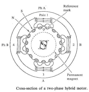
Stepper motor is a device used to obtain an accurate position control of rotating shafts. A stepper motor employs rotation of its shaft in terms of steps, rather than continuous rotation as in case of AC or DC motor. To rotate the shaft of the stepper motor, a sequence of pulses is needed to be applied to the windings of the stepper motor, in proper sequence. The numbers of pulses required for complete rotation of the shaft of the stepper motor are equal to the number of internal teeth on its rotor. The stator teeth and the rotor teeth lock with each other to fix a position of the shaft. With a pulse applied to the winding input, the rotor rotates by one teeth position or an angle x. the angle x may be calculated as.
x = 3600 / no. of rotor teeth
After the rotation of the shaft through angle x, the rotor locks it self with the next tooth in the sequence on the internal surface of the stator. The typical schematic of a typical stepper motor with four windings is as shown below.
 The stepper motors have been designed to work with digital circuits. Binary level pulses of 0-5V are required at its winding inputs to obtain the rotation of the shafts. The sequence of the pulses can be decided, depending upon the required motion of the shaft. By suitable sequence of the pulses the motor can be used in three modes of operation.
WORKING:-
8255 is interfaced with 8086 in I/O mapped I/O. port C (PC0, PC1, PC2, PC3) is used to give pulse sequence to stepper motor. The 8255 provides very less current which will not be able to drive stepper motor coils so each of the winding of a stepper motor needs to be interfaced using high speed switching Darlington transistors with max 1A, 80V rating with heat sink, with the output port of 8255. Output the sequence in correct order to have the desired direction to rotate the motor.
Assembly Language Program to rotate Stepper Motor in Clockwise direction
MODEL SMALL
.STACK 100
.DATA
PORTA EQU FFC0H ; PORTA ADDRESS
PORTB EQU FFC2H ; PORTB ADDRESS
PORTC EQU FFC4H ; PORTC ADDRESS
CWR EQU FFC6H ; CONTROL PORT ADDRESS
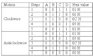
PHASEC EQU 03H
PHASEB EQU 06H ; SEQUENCE IN SERIES TO ROTATE MOTOR
PHASED EQU 0CH ; IN CLOCKWISE DIRECTION
PHASEA EQU 09H
.CODE
START:
MOV AL,@DATA
MOV DX,CTL
OUT DX,AL
AGAIN:
MOV AL,PHASEC
MOV DX,PORTC
OUT DX,AL
MOV CX,0FFFFH
UP:
LOOP UP
MOV AL,PHASEB
MOV DX,PORTC
OUT DX,AL
MOV CX,0FFFFH
UP1:
LOOP UP1
MOV AL,PHASED
MOV DX,PORTC
OUT DX,AL
MOV CX,0FFFFH
UP2:
LOOP UP2
MOV AL,PHASEA
MOV DX,PORTC
OUT DX,AL
MOV CX,0FFFFH
UP3:
LOOP UP3
JMP AGAIN ; REPEATE OUTPUT SEQUENCE
INT 03H
END START
Assembly Language Program to rotate Stepper Motor in Anticlockwise direction
MODEL SMALL
.STACK 100
.DATA
PORTA EQU FFC0H ; PORTA ADDRESS
PORTB EQU FFC2H ; PORTB ADDRESS
PORTC EQU FFC4H ; PORTC ADDRESS
CWR EQU FFC6H ; CONTROL PORT ADDRESS
PHASEC EQU 03H
PHASEA EQU 09H ; SEQUENCE IN SERIES TO ROTATE MOTOR
PHASED EQU 0CH ; IN ANTICLOCKWISE DIRECTION
PHASEB EQU 06H
.CODE
START:
MOV AL,@DATA
MOV DX,CTL
OUT DX,AL
AGAIN:
MOV AL,PHASEC
MOV DX,PORTC
OUT DX,AL
MOV CX,0FFFFH
UP:
LOOP UP
MOV AL,PHASEA
MOV DX,PORTC
OUT DX,AL
MOV CX,0FFFFH
UP1:
LOOP UP1
MOV AL,PHASED
MOV DX,PORTC
OUT DX,AL
MOV CX,0FFFFH
UP2:
LOOP UP2
MOV AL,PHASEB
MOV DX,PORTC
OUT DX,AL
MOV CX,0FFFFH
UP3:
LOOP UP3
JMP AGAIN ; REPEATE OUTPUT SEQUENCE
INT 03H
END START
PROCEDURE:-
1. Connect power supply 5V & GND to both microprocessor trainer kit & Stepper motor interfacing kit.
2. Connect data bus between microprocessor trainer kit & Stepper motor interfacing kit.
3. Enter the program to rotate Stepper motor in clockwise & anticlockwise.
4. Execute the program by typing GO E000:00C0 ENTER for clockwise, GO E000:0030 ENTER for anticlockwise.
5. Observe the rotation of stepper motor.
You might be also interested in:
:: Temperature Control system using 8086
:: Traffic light control system using 8086
:: Assembly Language Program to serve NMI
APPARATUS:-
Microprocessor trainer kit, ADC kit, power supply, data cable etc
THEORY:-
Stepper motor is a device used to obtain an accurate position control of rotating shafts. A stepper motor employs rotation of its shaft in terms of steps, rather than continuous rotation as in case of AC or DC motor. To rotate the shaft of the stepper motor, a sequence of pulses is needed to be applied to the windings of the stepper motor, in proper sequence. The numbers of pulses required for complete rotation of the shaft of the stepper motor are equal to the number of internal teeth on its rotor. The stator teeth and the rotor teeth lock with each other to fix a position of the shaft. With a pulse applied to the winding input, the rotor rotates by one teeth position or an angle x. the angle x may be calculated as.
x = 3600 / no. of rotor teeth
After the rotation of the shaft through angle x, the rotor locks it self with the next tooth in the sequence on the internal surface of the stator. The typical schematic of a typical stepper motor with four windings is as shown below.
 The stepper motors have been designed to work with digital circuits. Binary level pulses of 0-5V are required at its winding inputs to obtain the rotation of the shafts. The sequence of the pulses can be decided, depending upon the required motion of the shaft. By suitable sequence of the pulses the motor can be used in three modes of operation.
- One phase ON (medium torque)
- Two phase ON (high torque)
- Half stepping (low torque)

WORKING:-
8255 is interfaced with 8086 in I/O mapped I/O. port C (PC0, PC1, PC2, PC3) is used to give pulse sequence to stepper motor. The 8255 provides very less current which will not be able to drive stepper motor coils so each of the winding of a stepper motor needs to be interfaced using high speed switching Darlington transistors with max 1A, 80V rating with heat sink, with the output port of 8255. Output the sequence in correct order to have the desired direction to rotate the motor.
Assembly Language Program to rotate Stepper Motor in Clockwise direction
MODEL SMALL
.STACK 100
.DATA
PORTA EQU FFC0H ; PORTA ADDRESS
PORTB EQU FFC2H ; PORTB ADDRESS
PORTC EQU FFC4H ; PORTC ADDRESS
CWR EQU FFC6H ; CONTROL PORT ADDRESS
PHASEC EQU 03H
PHASEB EQU 06H ; SEQUENCE IN SERIES TO ROTATE MOTOR
PHASED EQU 0CH ; IN CLOCKWISE DIRECTION
PHASEA EQU 09H
.CODE
START:
MOV AL,@DATA
MOV DX,CTL
OUT DX,AL
AGAIN:
MOV AL,PHASEC
MOV DX,PORTC
OUT DX,AL
MOV CX,0FFFFH
UP:
LOOP UP
MOV AL,PHASEB
MOV DX,PORTC
OUT DX,AL
MOV CX,0FFFFH
UP1:
LOOP UP1
MOV AL,PHASED
MOV DX,PORTC
OUT DX,AL
MOV CX,0FFFFH
UP2:
LOOP UP2
MOV AL,PHASEA
MOV DX,PORTC
OUT DX,AL
MOV CX,0FFFFH
UP3:
LOOP UP3
JMP AGAIN ; REPEATE OUTPUT SEQUENCE
INT 03H
END START
Assembly Language Program to rotate Stepper Motor in Anticlockwise direction
MODEL SMALL
.STACK 100
.DATA
PORTA EQU FFC0H ; PORTA ADDRESS
PORTB EQU FFC2H ; PORTB ADDRESS
PORTC EQU FFC4H ; PORTC ADDRESS
CWR EQU FFC6H ; CONTROL PORT ADDRESS
PHASEC EQU 03H
PHASEA EQU 09H ; SEQUENCE IN SERIES TO ROTATE MOTOR
PHASED EQU 0CH ; IN ANTICLOCKWISE DIRECTION
PHASEB EQU 06H
.CODE
START:
MOV AL,@DATA
MOV DX,CTL
OUT DX,AL
AGAIN:
MOV AL,PHASEC
MOV DX,PORTC
OUT DX,AL
MOV CX,0FFFFH
UP:
LOOP UP
MOV AL,PHASEA
MOV DX,PORTC
OUT DX,AL
MOV CX,0FFFFH
UP1:
LOOP UP1
MOV AL,PHASED
MOV DX,PORTC
OUT DX,AL
MOV CX,0FFFFH
UP2:
LOOP UP2
MOV AL,PHASEB
MOV DX,PORTC
OUT DX,AL
MOV CX,0FFFFH
UP3:
LOOP UP3
JMP AGAIN ; REPEATE OUTPUT SEQUENCE
INT 03H
END START
PROCEDURE:-
1. Connect power supply 5V & GND to both microprocessor trainer kit & Stepper motor interfacing kit.
2. Connect data bus between microprocessor trainer kit & Stepper motor interfacing kit.
3. Enter the program to rotate Stepper motor in clockwise & anticlockwise.
4. Execute the program by typing GO E000:00C0 ENTER for clockwise, GO E000:0030 ENTER for anticlockwise.
5. Observe the rotation of stepper motor.
You might be also interested in:
:: Temperature Control system using 8086
:: Traffic light control system using 8086
:: Assembly Language Program to serve NMI
Subscribe to:
Posts (Atom)
