Program to interface DAC using 8255 and generate ramp waveform
The following is the assembly language using DAC to interface with 8255 and generate a ramp on CRO. Here in the code, we use two jump instructions JMP and JZ in order to form the ramp wave. The jump instructions used in the program are iterated to repeat cycles of a ramp wave.
Code:
MOV DX,8807 : DX is loaded with control word register address of 8255
MOV AL,80
OUT DX,AL : Contents of AL are transferred to portA of 8255
MOV DX,8801 : DX is loaded with Port A address of 8255
Ramp MOV AL,00
Begin OUT DX,AL ; Contents of AL are transferred to portA of 8255
INC AL
CMP AL,FF
JZ Ramp
JMP Begin ; Repeat the same
Thus we programed in assembly language to interface DAC using 8255 to generate a ramp wave.
Related links
Ebooks for micro processors and micro controllers
Showing posts with label 8255. Show all posts
Showing posts with label 8255. Show all posts
Oct 21, 2008
Program to interface DAC using 8255 and generate square waveform

Program to interface DAC using 8255 and generate square waveform
The following is the assembly language using DAC to interface with 8255 and generate a square wave on CRO. Here in the code, we use two delay elements one for the rising part of the wave and the other delay element to reach zero i.e decrement. Certain value chosen is delayed or sustained for a time period to form the square wave. The two loops used in the program are iterated to repeat cycles of a square wave.
Code:
MOV DX,8807 : DX is loaded with control word register address of 8255
MOV AL,80
OUT DX,AL : Contents of AL are transferred to portA of 8255
MOV DX,8801 : DX is loaded with Port A address of 8255
Begin MOV AL,00
OUT DX,AL ; Contents of AL are transferred to portA of 8255
MOV CX,00FF
Delay1 Loop Delay1
MOV AL,FF
OUT DX,AL : Contents of AL are transferred to portA of 8255
MOV CX,00FF : CX is loaded with 00FFH
Delay2 Loop Delay2 : Repeat until CX=0
JMP Begin ; Repeat the same
The expected square wave can be observed as in the figure shown. Thus we programed in assembly language to interface DAC using 8255 to generate a square waveform.
Related links
Ebooks for micro processors and micro controllers
Sep 5, 2008
8085 based projects for students
You can create following 8085 project using 8255
1. Traffic Light Control System
2. Controlling The Stepper Motor
3. Temperature Control System
4. Blinking LEDs In Circular Pattern
Out of these four projects, blinking LEDs in circular pattern is very simple as hardware required to create this project is minimum and coding is also very easy....
Temperature Control System needs sensing circuitry, analog to digital converter and circuit required to control the controller making project quite difficult.
Project On Controlling The Stepper Motor is easy. Its coding is the simplest but it obviously need one working stepper motor.
Traffic Light Control System is also a good project to opt for but it requires around 12 transistors and 12 relays.
You might be also interested in:
:: Temperature Control system using 8086
:: Traffic light control system using 8086
:: Assembly Language Program to serve NMI
:: Interfacing Stepper Motor to 8086 using 8255
Feb 19, 2008
Assembly Language Program to be executed when NMI is generated
Assembly Language Program to be executed when NMI is generated
AIM:To write Assembly Language Program to be executed when NMI is generated
APPARATUS:-
Microprocessor trainer kit & power supply.
NON MASKABLE INTERRUPT (NMI)
NMI is an edge triggered input pin which causes Type-2 interrupt. The NMI is not mask able internally by software. A transition from low to high initiates the interrupt response at the end of the current instruction. This input is internally synchronized.
When an external device interrupts the CPU at the interrupt pin NMI and the CPU is executing an instruction of a program. The CPU first completes the execution of current instruction. The IP is then incremented by one to point next instruction. The CPU then acknowledges the requesting device on its INTA pin immediately for NMI. After an interrupt is acknowledged, the CPU computes the vector address from the type of the interrupt that may be passed to interrupt structure of the CPU internally or externally (for NMI vector address is 00008 H). The contents of PSW, CS & IP are next pushed on stack. The contents of IP & CS now points to the address of the next instruction in main program from which the execution is to be continued after executing the ISR. The control is then transferred to Interrupt Service Routine for serving the interrupting device. The new address is found out from the interrupt vector table (for NMI [00009:00008] = ISR IP & [0000B:0000A] = ISR CS. The execution of ISR starts. At the end of ISR the last instruction should be IRET. When CPU executes IRET instruction the IP, CS & PSW is popped back from the stack and the execution continued from address received by IP & CS.
WRITE THIS PROGRAM AT 0000:4000 H MEMORY LOCATION AND EXECUTE IT
NOW PRESS NMI BUTTON ON 8086 MICROPROCESSOR KIT
You might be also interested in:
:: MASM 611 SOFTWARE
:: bit reversal and sorting programs
:: Find Square Root of a hexadecimal number in assembly language
:: common intreview questions on 8086
AIM:To write Assembly Language Program to be executed when NMI is generated
APPARATUS:-
Microprocessor trainer kit & power supply.
NON MASKABLE INTERRUPT (NMI)
NMI is an edge triggered input pin which causes Type-2 interrupt. The NMI is not mask able internally by software. A transition from low to high initiates the interrupt response at the end of the current instruction. This input is internally synchronized.
When an external device interrupts the CPU at the interrupt pin NMI and the CPU is executing an instruction of a program. The CPU first completes the execution of current instruction. The IP is then incremented by one to point next instruction. The CPU then acknowledges the requesting device on its INTA pin immediately for NMI. After an interrupt is acknowledged, the CPU computes the vector address from the type of the interrupt that may be passed to interrupt structure of the CPU internally or externally (for NMI vector address is 00008 H). The contents of PSW, CS & IP are next pushed on stack. The contents of IP & CS now points to the address of the next instruction in main program from which the execution is to be continued after executing the ISR. The control is then transferred to Interrupt Service Routine for serving the interrupting device. The new address is found out from the interrupt vector table (for NMI [00009:00008] = ISR IP & [0000B:0000A] = ISR CS. The execution of ISR starts. At the end of ISR the last instruction should be IRET. When CPU executes IRET instruction the IP, CS & PSW is popped back from the stack and the execution continued from address received by IP & CS.
WRITE THIS PROGRAM AT 0000:4000 H MEMORY LOCATION AND EXECUTE IT
0000:4000 MOV AX,0FFFFH
0000:4003 MOV BX,0FFFFH
0000:4006 ADD AX,BX
0000:4008 HLT
0000:4009 WRITE THIS PROGRAM AT 0000:4100 H MEMORY LOCATION AND EXECUTE IT0000:4100 MOV AX,0000H
0000:4103 MOV DS,AX
0000:4105 MOV AL,00H
0000:4107 MOV [0008],AL
0000:410A MOV AL,40H
0000:410C MOV [0009],AL
0000:410F MOV AL,00H
0000:4111 MOV [000A],AL
0000:4114 MOV AL,00H
0000:4116 MOV [000B],AL
0000:4119 HLT
0000:411A NOW PRESS NMI BUTTON ON 8086 MICROPROCESSOR KIT
You might be also interested in:
:: MASM 611 SOFTWARE
:: bit reversal and sorting programs
:: Find Square Root of a hexadecimal number in assembly language
:: common intreview questions on 8086
Jan 22, 2008
Interfacing Stepper Motor to 8086 using 8255
To Interface Stepper Motor to 8086 using 8255 and write Assembly Language Program to rotate Stepper Motor in Clockwise & Anticlockwise direction.
APPARATUS:-
Microprocessor trainer kit, ADC kit, power supply, data cable etc
THEORY:-
Stepper motor is a device used to obtain an accurate position control of rotating shafts. A stepper motor employs rotation of its shaft in terms of steps, rather than continuous rotation as in case of AC or DC motor. To rotate the shaft of the stepper motor, a sequence of pulses is needed to be applied to the windings of the stepper motor, in proper sequence. The numbers of pulses required for complete rotation of the shaft of the stepper motor are equal to the number of internal teeth on its rotor. The stator teeth and the rotor teeth lock with each other to fix a position of the shaft. With a pulse applied to the winding input, the rotor rotates by one teeth position or an angle x. the angle x may be calculated as.
x = 3600 / no. of rotor teeth
After the rotation of the shaft through angle x, the rotor locks it self with the next tooth in the sequence on the internal surface of the stator. The typical schematic of a typical stepper motor with four windings is as shown below.
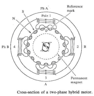 The stepper motors have been designed to work with digital circuits. Binary level pulses of 0-5V are required at its winding inputs to obtain the rotation of the shafts. The sequence of the pulses can be decided, depending upon the required motion of the shaft. By suitable sequence of the pulses the motor can be used in three modes of operation.
WORKING:-
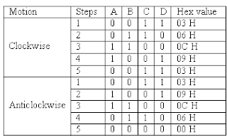
8255 is interfaced with 8086 in I/O mapped I/O. port C (PC0, PC1, PC2, PC3) is used to give pulse sequence to stepper motor. The 8255 provides very less current which will not be able to drive stepper motor coils so each of the winding of a stepper motor needs to be interfaced using high speed switching Darlington transistors with max 1A, 80V rating with heat sink, with the output port of 8255. Output the sequence in correct order to have the desired direction to rotate the motor.
Assembly Language Program to rotate Stepper Motor in Clockwise direction
MODEL SMALL
.STACK 100
.DATA
PORTA EQU FFC0H ; PORTA ADDRESS
PORTB EQU FFC2H ; PORTB ADDRESS
PORTC EQU FFC4H ; PORTC ADDRESS
CWR EQU FFC6H ; CONTROL PORT ADDRESS
PHASEC EQU 03H
PHASEB EQU 06H ; SEQUENCE IN SERIES TO ROTATE MOTOR
PHASED EQU 0CH ; IN CLOCKWISE DIRECTION
PHASEA EQU 09H
.CODE
START:
MOV AL,@DATA
MOV DX,CTL
OUT DX,AL
AGAIN:
MOV AL,PHASEC
MOV DX,PORTC
OUT DX,AL
MOV CX,0FFFFH
UP:
LOOP UP
MOV AL,PHASEB
MOV DX,PORTC
OUT DX,AL
MOV CX,0FFFFH
UP1:
LOOP UP1
MOV AL,PHASED
MOV DX,PORTC
OUT DX,AL
MOV CX,0FFFFH
UP2:
LOOP UP2
MOV AL,PHASEA
MOV DX,PORTC
OUT DX,AL
MOV CX,0FFFFH
UP3:
LOOP UP3
JMP AGAIN ; REPEATE OUTPUT SEQUENCE
INT 03H
END START
Assembly Language Program to rotate Stepper Motor in Anticlockwise direction
MODEL SMALL
.STACK 100
.DATA
PORTA EQU FFC0H ; PORTA ADDRESS
PORTB EQU FFC2H ; PORTB ADDRESS
PORTC EQU FFC4H ; PORTC ADDRESS
CWR EQU FFC6H ; CONTROL PORT ADDRESS
PHASEC EQU 03H
PHASEA EQU 09H ; SEQUENCE IN SERIES TO ROTATE MOTOR
PHASED EQU 0CH ; IN ANTICLOCKWISE DIRECTION
PHASEB EQU 06H
.CODE
START:
MOV AL,@DATA
MOV DX,CTL
OUT DX,AL
AGAIN:
MOV AL,PHASEC
MOV DX,PORTC
OUT DX,AL
MOV CX,0FFFFH
UP:
LOOP UP
MOV AL,PHASEA
MOV DX,PORTC
OUT DX,AL
MOV CX,0FFFFH
UP1:
LOOP UP1
MOV AL,PHASED
MOV DX,PORTC
OUT DX,AL
MOV CX,0FFFFH
UP2:
LOOP UP2
MOV AL,PHASEB
MOV DX,PORTC
OUT DX,AL
MOV CX,0FFFFH
UP3:
LOOP UP3
JMP AGAIN ; REPEATE OUTPUT SEQUENCE
INT 03H
END START
PROCEDURE:-
1. Connect power supply 5V & GND to both microprocessor trainer kit & Stepper motor interfacing kit.
2. Connect data bus between microprocessor trainer kit & Stepper motor interfacing kit.
3. Enter the program to rotate Stepper motor in clockwise & anticlockwise.
4. Execute the program by typing GO E000:00C0 ENTER for clockwise, GO E000:0030 ENTER for anticlockwise.
5. Observe the rotation of stepper motor.
You might be also interested in:
:: Temperature Control system using 8086
:: Traffic light control system using 8086
:: Assembly Language Program to serve NMI
APPARATUS:-
Microprocessor trainer kit, ADC kit, power supply, data cable etc
THEORY:-
Stepper motor is a device used to obtain an accurate position control of rotating shafts. A stepper motor employs rotation of its shaft in terms of steps, rather than continuous rotation as in case of AC or DC motor. To rotate the shaft of the stepper motor, a sequence of pulses is needed to be applied to the windings of the stepper motor, in proper sequence. The numbers of pulses required for complete rotation of the shaft of the stepper motor are equal to the number of internal teeth on its rotor. The stator teeth and the rotor teeth lock with each other to fix a position of the shaft. With a pulse applied to the winding input, the rotor rotates by one teeth position or an angle x. the angle x may be calculated as.
x = 3600 / no. of rotor teeth
After the rotation of the shaft through angle x, the rotor locks it self with the next tooth in the sequence on the internal surface of the stator. The typical schematic of a typical stepper motor with four windings is as shown below.
 The stepper motors have been designed to work with digital circuits. Binary level pulses of 0-5V are required at its winding inputs to obtain the rotation of the shafts. The sequence of the pulses can be decided, depending upon the required motion of the shaft. By suitable sequence of the pulses the motor can be used in three modes of operation.
- One phase ON (medium torque)
- Two phase ON (high torque)
- Half stepping (low torque)

WORKING:-
8255 is interfaced with 8086 in I/O mapped I/O. port C (PC0, PC1, PC2, PC3) is used to give pulse sequence to stepper motor. The 8255 provides very less current which will not be able to drive stepper motor coils so each of the winding of a stepper motor needs to be interfaced using high speed switching Darlington transistors with max 1A, 80V rating with heat sink, with the output port of 8255. Output the sequence in correct order to have the desired direction to rotate the motor.
Assembly Language Program to rotate Stepper Motor in Clockwise direction
MODEL SMALL
.STACK 100
.DATA
PORTA EQU FFC0H ; PORTA ADDRESS
PORTB EQU FFC2H ; PORTB ADDRESS
PORTC EQU FFC4H ; PORTC ADDRESS
CWR EQU FFC6H ; CONTROL PORT ADDRESS
PHASEC EQU 03H
PHASEB EQU 06H ; SEQUENCE IN SERIES TO ROTATE MOTOR
PHASED EQU 0CH ; IN CLOCKWISE DIRECTION
PHASEA EQU 09H
.CODE
START:
MOV AL,@DATA
MOV DX,CTL
OUT DX,AL
AGAIN:
MOV AL,PHASEC
MOV DX,PORTC
OUT DX,AL
MOV CX,0FFFFH
UP:
LOOP UP
MOV AL,PHASEB
MOV DX,PORTC
OUT DX,AL
MOV CX,0FFFFH
UP1:
LOOP UP1
MOV AL,PHASED
MOV DX,PORTC
OUT DX,AL
MOV CX,0FFFFH
UP2:
LOOP UP2
MOV AL,PHASEA
MOV DX,PORTC
OUT DX,AL
MOV CX,0FFFFH
UP3:
LOOP UP3
JMP AGAIN ; REPEATE OUTPUT SEQUENCE
INT 03H
END START
Assembly Language Program to rotate Stepper Motor in Anticlockwise direction
MODEL SMALL
.STACK 100
.DATA
PORTA EQU FFC0H ; PORTA ADDRESS
PORTB EQU FFC2H ; PORTB ADDRESS
PORTC EQU FFC4H ; PORTC ADDRESS
CWR EQU FFC6H ; CONTROL PORT ADDRESS
PHASEC EQU 03H
PHASEA EQU 09H ; SEQUENCE IN SERIES TO ROTATE MOTOR
PHASED EQU 0CH ; IN ANTICLOCKWISE DIRECTION
PHASEB EQU 06H
.CODE
START:
MOV AL,@DATA
MOV DX,CTL
OUT DX,AL
AGAIN:
MOV AL,PHASEC
MOV DX,PORTC
OUT DX,AL
MOV CX,0FFFFH
UP:
LOOP UP
MOV AL,PHASEA
MOV DX,PORTC
OUT DX,AL
MOV CX,0FFFFH
UP1:
LOOP UP1
MOV AL,PHASED
MOV DX,PORTC
OUT DX,AL
MOV CX,0FFFFH
UP2:
LOOP UP2
MOV AL,PHASEB
MOV DX,PORTC
OUT DX,AL
MOV CX,0FFFFH
UP3:
LOOP UP3
JMP AGAIN ; REPEATE OUTPUT SEQUENCE
INT 03H
END START
PROCEDURE:-
1. Connect power supply 5V & GND to both microprocessor trainer kit & Stepper motor interfacing kit.
2. Connect data bus between microprocessor trainer kit & Stepper motor interfacing kit.
3. Enter the program to rotate Stepper motor in clockwise & anticlockwise.
4. Execute the program by typing GO E000:00C0 ENTER for clockwise, GO E000:0030 ENTER for anticlockwise.
5. Observe the rotation of stepper motor.
You might be also interested in:
:: Temperature Control system using 8086
:: Traffic light control system using 8086
:: Assembly Language Program to serve NMI
Jan 17, 2008
Interfacing Digital-To-Analog converter to 8086 using 8255

- Assembly Language Program to generate Square Wave
- Assembly Language Program to generate Ramp Wave
- Assembly Language Program to generate Triangular Wave
- Assembly Language Program to generate Staircase Wave
AIM:-
To Interface Digital -to-Analog converter to 8086 using 8255 and write Assembly Language Program to generate Square Wave, Ramp Wave, Triangular Wave & Staircase Wave form.
APPARATUS:-
Microprocessor trainer kit, ADC kit, power supply, data cable, CRO etc
THEORY:-
The DAC 0800 is a monolithic 8 bit high speed current output digital to analog converters featuring setting time of 100nSEC. It also features high compliance complementary current outputs to allow differential output voltage of 20 Vp-p with simple resistor load and it can be operated both in unipolar and bipolar mode.
FEATURES:-
- Fast setting output current 100nS
- Full scale error +/- 1 LSB
- Complementary current outputs
- easy interface to all microprocessor
- Wide power supply range +/- 4.5 to +/- 18V
- low power consumption
WORKING:-
When chip select of DAC is enabled then DAC will convert digital input value given through portliness PB0-PB7 to analog value. The analog output from DAC is a current quantity. This current is converted to voltage using OPAMP based current-to-voltage converter. The voltage outputs (+/- 5V for bipolar 0 to 5V for unipolar mode) of OPAMP are connected to CRO to see the wave form.
; RAMP WAVE GENERATOR with 8086 using 8255
MODEL SMALL
.STACK 100
.DATA
CONTROL EQU 0FFC6H ; Control port address for 8255
PORTA EQU 0FFC0H ; Port A address for 8255
PORTB EQU 0FFC2H ; Port B address for 8255
PORTC EQU 0FFC4H ; Port C address for 8255
.CODE
START:
MOV AX,@DATA ;Initialize Data segment
MOV DS,AX
MOV DX,CONTROL
MOV AL,80H ;Initialize all ports as output
OUT DX,AL ;Ports
MOV BL,FFH ;Take FFH in BL analog equivalent to 5V
RAMP : MOV DX,PORTB
MOV AL,BL ;Copy to AL
OUT DX,AL ;And output it on the port
DEC BL ; To generate ramp wave this 5V is continuously decreased till 0V
JNZ RAMP ; Jump to RAMP if not 0
MOV BL,FFH ; To generate same wave this procedure is repeated
JMP RAMP
INT 03H
END START
;SQUARE WAVE GENERATOR with 8086 using 8255
MODEL SMALL
.STACK 100
.DATA
CONTROL EQU 0FFC6H ; Control port address for 8255
PORTA EQU 0FFC0H ; Port A address for 8255
PORTB EQU 0FFC2H ; Port B address for 8255
PORTC EQU 0FFC4H ; Port C address for 8255
.CODE
START:
MOV DX,CONTROL
MOV AL,80H ; Initialize all ports as output
OUT DX,AL ; Ports
UP: MOV DX,PORTB
MOV AL,00H ;Output 00 for 0V level
CALL OUTPUT
MOV AL,0FFH ;Output FF for 5V level
CALL OUTPUT
JMP UP
OUTPUT:
OUT DX,AL
CALL DELAY
INT 21H
DELAY:
MOV CX,0FFH ; To vary through frequency alter the delay count
LUP1 LOOP LUP1
INT 21H
END START
;TRIANGULAR WAVE GENERATOR with 8086 using 8255
MODEL SMALL
.STACK 100
.DATA
CONTROL EQU 0FFC6H ; Control port address for 8255
PORTA EQU 0FFC0H ; Port A address for 8255
PORTB EQU 0FFC2H ; Port B address for 8255
PORTC EQU 0FFC4H ; Port C address for 8255
.CODE
START:
MOV DX,CONTROL
MOV AL,80H ; Initialize all ports as output
OUT DX,AL ; Ports
BEGIN:
MOV DX,PORTB
MOV AL,00H ; Output 00 for 0V level
UP: CALL OUTPUT
INC AL ; To raise wave from 0V to 5V increment AL
CMP AL,00H
JNZ UP ; Jump UP till rising edge is reached i.e. 5V
MOV AL,0FFH
UP1: CALL OUTPUT
DEC AL ; To fall wave from 5V to 0V decrement AL
CMP AL,0FFH
JNZ UP1 ; Jump UP till falling edge is reached i.e. 0V
JMP BEGIN
OUTPUT:
OUT DX,AL
CALL DELAY
INT 21H
DELAY:
MOV CX,07H ;To vary the frequency alter the delay count
LUP1:LOOP LUP1
INT 21H
END START
;STAIRCASE WAVEFORM GENERATOR with 8086 using 8255
MODEL SMALL
.STACK 100
.DATA
CONTROL EQU 0FFC6H ; Control port address for 8255
PORTA EQU 0FFC0H ; Port A address for 8255
PORTB EQU 0FFC2H ; Port B address for 8255
PORTC EQU 0FFC4H ; Port C address for 8255
.CODE
START:
MOV DX,CONTROL
MOV AL,80H ;Initialize all ports as output
OUT DX,AL ;Ports
UP: MOV DX,PORTB
MOV AL,00H ;Output 00 for 0V level
CALL OUTPUT ; And wait for some time
MOV AL,0FFH ;Output FF for 5V level
CALL OUTPUT ; And wait for some time
MOV AL,07FH ;Output 7F for 2.5V level
CALL OUTPUT ; And wait for some time
JMP UP
OUTPUT: OUT DX,AL
MOV CX,FFH
DELAY: LOOP DELAY ; To add DELAY
INT 03H
END START
PROCEDURE:-
- Connect power supply 5V & GND to both microprocessor trainer kit & DAC interfacing kit.
- Connect data bus between microprocessor trainer kit & DAC interfacing kit.
- Enter the program to generate Ramp, Square, Triangular & Staircase Wave.
- Execute the program by typing GO E000:4770 ENTER for Ramp, GO E000:03A0 ENTER for Square, GO E000:0410 ENTER for Triangular, GO E000:4890 ENTER for Staircase.
- Observe the wave forms on CRO.
:: Temperature Control system using 8086
:: Traffic light control system using 8086
:: Assembly Language Program to serve NMI
Subscribe to:
Posts (Atom)
