Google

Feb 25, 2010

Program for multiplexing of led displays for pic microcontrollers

Suppose you want to design the ac digital voltmeter rang up to 0-300v or above, by using any pic 8-bit mcu, and want to use 3, 7-segment display for it then there can be a problem as to how do you indicate such large value on display

then you can go with the following approch

use BCD to 7 segment converter, so that only 4 bits can be used to control a single 7 seven segment display..... so in total u need 12 output lines. you can get 12 output bits by using 2 different ports of any suitable 8 bit microcontroller. link to one such converter http://www.ee.washington.edu/stores/DataSheets/74ls/74ls47.pdf

use 7 bits from one port for all 3 displays and use 3 other bits to select led's this is done very fast so human eye can not make out that the displays are glowing sequencially and not continously.
here is sample code for pic

#include
#include

void DisplayNumber( unsigned int number );

void main()
{
trisb = 0;
trisa = 0xFF;

unsigned int randNumb = 0;

while( 1 )
{

while( porta.0 == 0 ) // wait for key pressed
DisplayNumber( randNumb ); // display number to keep display refreshed

// while key pressed increment counter
// Number will be random based on how long input is turned on
while( porta.0 == 1 )
{
randNumb++;
if( ++randNumb > 9999 )
randNumb = 0;
}

// display a series of random numbers so it looks like we are
char j;
for( j = 0; j < x =" rand();" i =" 0;" i =" 0x01;" i =" 0b1000;">>= 1 )
{
digit = number % 10;
number /= 10;

portb = digit & 0x0F;
portb = (digit & 0x0F) | (i <<>

Feb 20, 2010

version control system for keil & MPLAB.

Hi when you are working on large project which involve large number of programs and many developers work at same thing then thing will become hard to manage and the project may Fail.

so when you are dealing with Such kind of progects while developing Microprocessor microcontroller Projects it is all ways better to use CVS Code version system or Version control sytems.It is the best way to share code, you could do the same in MATLAB, Keil or MPlab but it is much efficient to use SVN.


Please find the bellow video to learn CVS/SVN

Tutorial: using tortoisesvn, subversion on windows from Mark Guzman on Vimeo.

Feb 17, 2010

LED blinking program for Pic microcontroller

Here is the program for Pic microcontroller PIC16F877A
to blink a LED connected to B3 of PORTC,

This program works for Mplab. or using HiTECH PRO Lite compiler.


PICClite code may be

#include
#include "delay.h"
#define _XTAL_FREQ 4000000
_CONFIG(MCLREN & UNPROTECT & BORDIS & WDTDIS & PWRTEN & INTIO);

void main()

{
TRISC=0;
while (1)
{
PORTC = 8;
DelayMs(250);DelayMs(250);
PORTC = 0;
DelayMs(250);DelayMs(250);
}

}

in PIC_Clite , "delay.h" has to be included because its MACRO, but in PRO its inbuilt

#include
#define _XTAL_FREQ 4000000
_CONFIG(MCLREN & UNPROTECT & BORDIS & WDTDIS & PWRTEN & INTIO);

void main()

{
TRISC=0;
while (1)
{
PORTC = 8;
__delay_ms(100);_delay_ms(100); // use this delay to test the code
__delay_ms(100);_delay_ms(100);
PORTC = 0;
__delay_ms(100);_delay_ms(100);
}

}
i didnt use _delay(100000); because whn Xtal Freq is high(20Mz) the delay changes & you will not be able to see the LEDs blinking. ensure that watchdog timer is disabled in _CONFIG, hope it works..

Feb 13, 2010

A microprocessor Program to convert BCD pack and Unpack number for 8085.

Please find the Below program to Pack the two unpacked BCD numbers stored in memory locations 4200H and 4201H and store result in memory location 4300H. Assume the least significant digit is stored at 4200H.


Here is the Sample problem:
(4200H) = 04
(4201H) = 09
Result = (4300H) = 94


Source program for the above logic

LDA 4201H : Get the Most significant BCD digit
RLC
RLC
RLC
RLC : Adjust the position of the second digit (09 is changed to 90)
ANI FOH : Make least significant BCD digit zero
MOV C, A : store the partial result
LDA 4200H : Get the lower BCD digit
ADD C : Add lower BCD digit
STA 4300H : Store the result
HLT : Terminate program execution

Jan 10, 2010

How to measure + and - 5 Volts using PIC microcontroller PIC1F4550

This post will explain you how to measure postitive and Negative 5 voltage using PIC microcontroller PIC1F4550

First config the ADC channel in your controller and in the ADCON Registers you have an option to select +Vref & -Vref values. say ADC is 10bit resolution i.e. 2^10 you will get max count from 0 to 1024. so the count "0" indicates your -Vref (-5v) value, count "512" indicates the 0V and the Max count 1024 indicates your +Vref (+5v).
so that is how you can calculate the Voltage

But there is the porblem with the Above approch as we cannot use -ve voltage greater that -0.3 with pic microcontroller which will permanently damage the PIC so first convert this range to 0 to 5 by some analog circuitry and then use it.

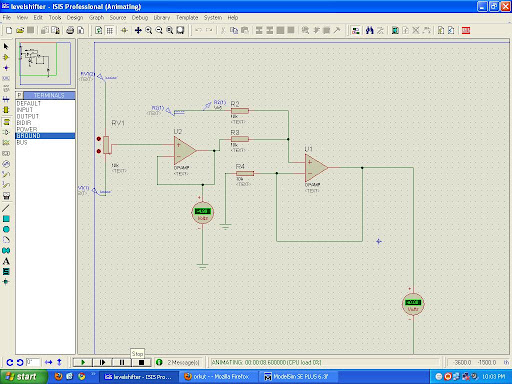
Here is the Circut for converting -5 - +5 to 0 - +5 voltage level.

Oct 15, 2009

Dely loop in AVR

Amer:

Hello freinds.
Can anybody help me regarding how to write a assembly language delay loop (loop-in-loop method no use of internal timers) for AVR microcontroller and how to evaluate the time delay provided by a loop?
I have an example of such loop taken from EFY mag's Nov.05 issue. You can help me by explaining the calculations for that code. The code goes as follows:-


delay: clr r19
ldi r17,$ff
loop1: inc r17
brne loop1
inc r19
brne loop1
ret
Please include the step by step calculation procedure for the delay loop in your reply so that i will be able to write loops for desired delay.
Also does anybody has another type of such code to generate delay? please explain the evaluation of the same.
Thanks in advance...

Arun Dayal
May be my C code for PWM Servo controller routine help u! Just follow my web at http://www.dayalsoft.com . An ASM delay can be written similarly. The routine is not using any of the internal timers and produces a variable delay ranging from 800 to 1250 uS precisely.

sajiD
main:
ser r16
loop1:
dec r16
brnq loop1
ret
that is very ez ok

Prasanna.S

for calulation of delay loop you should know the clock cycle period(i.e1/frequency) once you get this if you are writing code in assembly language you have to check no. of cyles required for each instruction(but for avr most of the instruction are single cycle)
refer processor manual write a simlpe code with decrement in loops the value to be given is calculated
no to be decremented=sec required/(no of cycles /loop)*period in sec

to exact value you have to consider the jump instruction in the end of loop completion etc.