Google

Jan 10, 2010

How to measure + and - 5 Volts using PIC microcontroller PIC1F4550

This post will explain you how to measure postitive and Negative 5 voltage using PIC microcontroller PIC1F4550

First config the ADC channel in your controller and in the ADCON Registers you have an option to select +Vref & -Vref values. say ADC is 10bit resolution i.e. 2^10 you will get max count from 0 to 1024. so the count "0" indicates your -Vref (-5v) value, count "512" indicates the 0V and the Max count 1024 indicates your +Vref (+5v).
so that is how you can calculate the Voltage

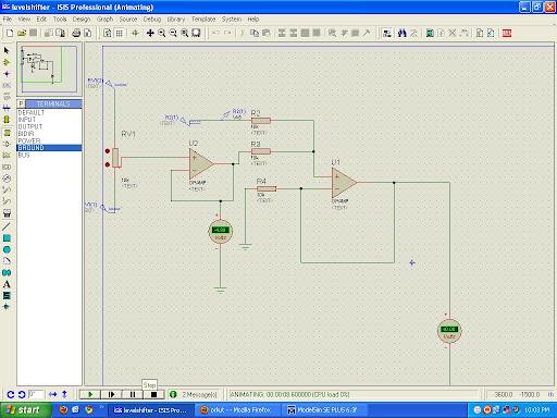
But there is the porblem with the Above approch as we cannot use -ve voltage greater that -0.3 with pic microcontroller which will permanently damage the PIC so first convert this range to 0 to 5 by some analog circuitry and then use it.

Here is the Circut for converting -5 - +5 to 0 - +5 voltage level.
Oct 15, 2009

Dely loop in AVR

Amer:

Hello freinds.
Can anybody help me regarding how to write a assembly language delay loop (loop-in-loop method no use of internal timers) for AVR microcontroller and how to evaluate the time delay provided by a loop?
I have an example of such loop taken from EFY mag's Nov.05 issue. You can help me by explaining the calculations for that code. The code goes as follows:-


delay: clr r19
ldi r17,$ff
loop1: inc r17
brne loop1
inc r19
brne loop1
ret
Please include the step by step calculation procedure for the delay loop in your reply so that i will be able to write loops for desired delay.
Also does anybody has another type of such code to generate delay? please explain the evaluation of the same.
Thanks in advance...

Arun Dayal
May be my C code for PWM Servo controller routine help u! Just follow my web at http://www.dayalsoft.com . An ASM delay can be written similarly. The routine is not using any of the internal timers and produces a variable delay ranging from 800 to 1250 uS precisely.

sajiD
main:
ser r16
loop1:
dec r16
brnq loop1
ret
that is very ez ok

Prasanna.S

for calulation of delay loop you should know the clock cycle period(i.e1/frequency) once you get this if you are writing code in assembly language you have to check no. of cyles required for each instruction(but for avr most of the instruction are single cycle)
refer processor manual write a simlpe code with decrement in loops the value to be given is calculated
no to be decremented=sec required/(no of cycles /loop)*period in sec

to exact value you have to consider the jump instruction in the end of loop completion etc.

Oct 13, 2009

C Programming Options in AVR

I am new to AVRs
I want to know what all programming options are there for C.
I know about BASCOM, but dont personally like BASIC that much.

ans:

* hey try codvisionavr c compiler .....it good and easy to learn and when u become pro use
WinAVR GCC

* I think you should see the page http://www.lancos.com and everthing will be clear! U will be able to make ur own circuit to program downloader circuit! as well as software to download for free!
U should use IAR Embedded C Compiler! It is widely supported by C Libraries and Evaluation version if free and sufficient for new users!

One of the International Journal Paper of mine for Your Use
http://www.convergencepromotions.com/atmelonline/v_9/pdf/AtmelJournal_V9_ConstructingA16-Channel.pdf

Similar ones u could find at http://www.atmel.com web site

* You may try AVRstudio from http://www.atmel.com/dyn/products/tools_card.asp?tool_id=2725 along with WINAVR from winavr.sourceforge.net/ . AVRstudio serves as the IDE and Debugger/Simulator and WINAVR the C compiler. Both complement each other.

For the hardware part you could try the JTAG emulator described in this site.
http://www.scienceprog.com/build-your-own-avr-jtagice-clone/

I have made the emulator using GP board and it works perfectly.

* i recommend you to use C Language for programming AVR microcontroller
C is quite commonly used for programming microcontrollers and a lot of help is
available on programming microcontroller in C
you can design your own programmer for AVR because AVR microcontroller has SPI & other ports for In-Circuit programming

Oct 5, 2009

How To to build an ISP for Atmega 128

You can check out Electronics For You Vol 31 nov 2005 edition

or

First of all ATMEGA 128 supports ISP. One can use the same ISP programmer used for ATMEGA 16/32 to burn a ATMEGA 128. In your target platform just take out the connections for SPI, (MISO, MOSI, SCK, and RESET) and connect those line to your ISP programmer. For schematic and PCB layout mail me : nibir.chakraborty@gmail.com. You can mention the details of the target board like what other things you want in the platform.

Jun 8, 2009

ADC on LPC2129

Here goes the second post on " How to program the onboard adc in LPC2129"
As said earlier LPC2129 has 4 onboard 10-bit ADC. Also these ADC's are internally multiplexed. So here i give out a snippet of how you could access the ADC's on LPC21xx.

At the time of writing this post,i dnt believe that any further explanation is needed . In case you need please refer to the end of line comment or feel free to comment ont he post.


#include "LPC21xx.H" // LPC21xx definitions


static unsigned short ADC_Config(unsigned char channel)
{
unsigned int i;
ADCR = 0x00200300 | ch; // Init ADC (Pclk = 12MHz) and select channel
ADCR |= 0x01000000; // Start A/D Conversion
do
{
i = ADDR; // Read A/D Data Register
} while ((i & 0x80000000) == 0); // Wait for end of A/D Conversion
return (i >> 6) & 0x03FF; // bit 6:15 is 10 bit AD value
}

int main(void)
{
while (1)
{
ADC_Config(2); // Access adc corresponding to the port
ADC_Config(4);

}
}

May 28, 2009

hola ! ARM

ARM-7 LPC2129

*MCU-> Microcontroller unit

This post is meant to introduce readers to a new platform. Presented here are few of the features of LPC2129. LPC2129 is a 32 bit MCU dev by the NXP semiconductors. It’s based on ARM 7 TDMI-s architecture. LPC 2129 is a very good tool for student projects coz it is readily available, and also costs reasonable.

Here are a few features of this MCU

· High-performance 32-bit RISC Microcontroller

· Thumb extensions

· 256KB on-chip Flash ROM

· In-System Programming (ISP) and In-Application Programming (IAP)

· 16KB RAM, Vectored Interrupt Controller,

· Two UARTs,

· I2C serial interface,

· 2 SPI serial interfaces

· Two timers (7 capture/compare channels),

· PWM unit with up to 6 PWM outputs,

· 4-channels 10bit ADC,

· 2 CAN channels.

· Real Time Clock,

· Watchdog Timer,

· General purpose I/O pins.

· CPU clock up to 60 MHz,

· On-chip crystal oscillator and

· On-chip PLL.