Google

Sep 1, 2015

Where to buy a raspberry Pi in india ?

Folks,


now a days its very easy to build cool project with raspberry pi which is a complete computer in a size of a credit card. and for your engineering projects you can use this wonderful product and build lot of interesting stuff like

1. personal media server at home
2. home automation
3. agriculture motor automation etc etc.
we will discuss on more of these projects in future but this post is about where we can buy the raspberry pi india,

option 1 buy it from amazon india. 
http://www.amazon.in/Raspberry-Pi-Model-Revision-512MB/dp/B009SQQF9C


option 2 : buying it from local distributors in india
there are few distributors in india who also supply raspberry pi india below are the list you can check out there website for the price and address 

Address: #34, 1st Floor, Sapthagiri Layout, Kothnur Dinne Main Road, Behind TR Hospital, 8th Phase, JP Nagar, Bengaluru, Karnataka 560076
Phone:1800 200 9993
price : 2635 for Model B+


kitsnspares
Online store: price is around

RS components
online store : price is around 2900 for model B+

PotentialLabs
online store : price is around 2395 for model B+


Option 3 buy from US and ship it to india,

if you are looking for some custom component something that is only available in amazon US or element14 in US you can always use services like http://www.borderlinx.com/IN/en to buy from US and ship them to india.

please do share your experience with buying raspberry pi india in the comments section


Mar 10, 2010

PWM with 89S52

Here is the program for Pulse width modulation PWM on basic for 89s52.

You could generate pwm using the following psedocode

#define high_period
#define low_period

main()
{
!!Code to initiate the timer;
!!Timer counter register value = high_period;
!!set port pin high
!!start timer
while(1);
}

interrupt void time_interrupt_routine(void)
{
if(port pin is high)
!!Timer counter register value = low_period;

else
!!Timer counter register value = high_period;

!!Toggle port pin
!! start timer;
}

Here high_period + low_period gives the time period in terms of clock cycle and

high_period/(high_period + low_period) *100 gives the dutycycle.

Mar 5, 2010

How to access R0 to R7 registers in Keil C?

you can use the following Program to access R0 to R7 registers in Keil C


{

unsigned char R0Val;

_asm

MOV A, R0
MOV _R0Val, A

_endasm

}

OR

{

unsigned char R0Val;

#pragma ASM

MOV A, R0
MOV _R0Val, A

#pragma ENDASM

}

C variables have to be prefixed by '_' or underscore character, to be accessible in the assembly section of the C code.

Hope this helps.

Feb 28, 2010

Program to initialise the LCD in 4 bit mode using PIC microcontroller

It was for 16F72 at 4Mhz written in cc5x. LCD is connected to PORTB.RS at RB7,RW at RB1,EN at RB6. DB7 at RB2,DB6 at RB3, DB5 at RB4, and DB4 at RB5. A function delay_ms() is used , which is not shown here.

code will work for 2x16 character LCD modules.

void lcdw(unsigned char m)
{
PORTB.2=m.7;
PORTB.3=m.6;
PORTB.4=m.5;
PORTB.5=m.4;
en=1;
nop();
nop();
en=0;
}

void nbw(unsigned char m)
{
PORTB.2=m.7;
PORTB.3=m.6;
PORTB.4=m.5;
PORTB.5=m.4;
en=1;
nop();
nop();
en=0;
PORTB.2=m.3;
PORTB.3=m.2;
PORTB.4=m.1;
PORTB.5=m.0;
en=1;
nop();
nop();
en=0;
}

void goadr(unsigned char a)
{

rs=0;
nbw(0x80 + a);
delay_ms(5); // delay of 5msec

}


void main()
{
................

TRISB=0;
PORTB=0;
rw=0;
rs=0;
lcdw(0x28); // lcdw function is only used once to initialise the LCD to 4 bit mode.
delay_ms(5);
nbw(0x28);
delay_ms(5);
nbw(0x0c);
delay_ms(5);
nbw(0x06);
delay_ms(5);
nbw(0x01);
delay_ms(5);
goadr(0x02);
rs=1;
nbw('a'); //displays the character "a" at location 0x02
nbw('b'); //displays the character "b" at location 0x03
.........................


}

Feb 25, 2010

Program for multiplexing of led displays for pic microcontrollers

Suppose you want to design the ac digital voltmeter rang up to 0-300v or above, by using any pic 8-bit mcu, and want to use 3, 7-segment display for it then there can be a problem as to how do you indicate such large value on display

then you can go with the following approch

use BCD to 7 segment converter, so that only 4 bits can be used to control a single 7 seven segment display..... so in total u need 12 output lines. you can get 12 output bits by using 2 different ports of any suitable 8 bit microcontroller. link to one such converter http://www.ee.washington.edu/stores/DataSheets/74ls/74ls47.pdf

use 7 bits from one port for all 3 displays and use 3 other bits to select led's this is done very fast so human eye can not make out that the displays are glowing sequencially and not continously.
here is sample code for pic

#include
#include

void DisplayNumber( unsigned int number );

void main()
{
trisb = 0;
trisa = 0xFF;

unsigned int randNumb = 0;

while( 1 )
{

while( porta.0 == 0 ) // wait for key pressed
DisplayNumber( randNumb ); // display number to keep display refreshed

// while key pressed increment counter
// Number will be random based on how long input is turned on
while( porta.0 == 1 )
{
randNumb++;
if( ++randNumb > 9999 )
randNumb = 0;
}

// display a series of random numbers so it looks like we are
char j;
for( j = 0; j < x =" rand();" i =" 0;" i =" 0x01;" i =" 0b1000;">>= 1 )
{
digit = number % 10;
number /= 10;

portb = digit & 0x0F;
portb = (digit & 0x0F) | (i <<>

Feb 20, 2010

version control system for keil & MPLAB.

Hi when you are working on large project which involve large number of programs and many developers work at same thing then thing will become hard to manage and the project may Fail.

so when you are dealing with Such kind of progects while developing Microprocessor microcontroller Projects it is all ways better to use CVS Code version system or Version control sytems.It is the best way to share code, you could do the same in MATLAB, Keil or MPlab but it is much efficient to use SVN.


Please find the bellow video to learn CVS/SVN

Tutorial: using tortoisesvn, subversion on windows from Mark Guzman on Vimeo.

Feb 17, 2010

LED blinking program for Pic microcontroller

Here is the program for Pic microcontroller PIC16F877A
to blink a LED connected to B3 of PORTC,

This program works for Mplab. or using HiTECH PRO Lite compiler.


PICClite code may be

#include
#include "delay.h"
#define _XTAL_FREQ 4000000
_CONFIG(MCLREN & UNPROTECT & BORDIS & WDTDIS & PWRTEN & INTIO);

void main()

{
TRISC=0;
while (1)
{
PORTC = 8;
DelayMs(250);DelayMs(250);
PORTC = 0;
DelayMs(250);DelayMs(250);
}

}

in PIC_Clite , "delay.h" has to be included because its MACRO, but in PRO its inbuilt

#include
#define _XTAL_FREQ 4000000
_CONFIG(MCLREN & UNPROTECT & BORDIS & WDTDIS & PWRTEN & INTIO);

void main()

{
TRISC=0;
while (1)
{
PORTC = 8;
__delay_ms(100);_delay_ms(100); // use this delay to test the code
__delay_ms(100);_delay_ms(100);
PORTC = 0;
__delay_ms(100);_delay_ms(100);
}

}
i didnt use _delay(100000); because whn Xtal Freq is high(20Mz) the delay changes & you will not be able to see the LEDs blinking. ensure that watchdog timer is disabled in _CONFIG, hope it works..

Feb 13, 2010

A microprocessor Program to convert BCD pack and Unpack number for 8085.

Please find the Below program to Pack the two unpacked BCD numbers stored in memory locations 4200H and 4201H and store result in memory location 4300H. Assume the least significant digit is stored at 4200H.


Here is the Sample problem:
(4200H) = 04
(4201H) = 09
Result = (4300H) = 94


Source program for the above logic

LDA 4201H : Get the Most significant BCD digit
RLC
RLC
RLC
RLC : Adjust the position of the second digit (09 is changed to 90)
ANI FOH : Make least significant BCD digit zero
MOV C, A : store the partial result
LDA 4200H : Get the lower BCD digit
ADD C : Add lower BCD digit
STA 4300H : Store the result
HLT : Terminate program execution

Jan 10, 2010

How to measure + and - 5 Volts using PIC microcontroller PIC1F4550

This post will explain you how to measure postitive and Negative 5 voltage using PIC microcontroller PIC1F4550

First config the ADC channel in your controller and in the ADCON Registers you have an option to select +Vref & -Vref values. say ADC is 10bit resolution i.e. 2^10 you will get max count from 0 to 1024. so the count "0" indicates your -Vref (-5v) value, count "512" indicates the 0V and the Max count 1024 indicates your +Vref (+5v).
so that is how you can calculate the Voltage

But there is the porblem with the Above approch as we cannot use -ve voltage greater that -0.3 with pic microcontroller which will permanently damage the PIC so first convert this range to 0 to 5 by some analog circuitry and then use it.

Here is the Circut for converting -5 - +5 to 0 - +5 voltage level.

Oct 15, 2009

Dely loop in AVR

Amer:

Hello freinds.
Can anybody help me regarding how to write a assembly language delay loop (loop-in-loop method no use of internal timers) for AVR microcontroller and how to evaluate the time delay provided by a loop?
I have an example of such loop taken from EFY mag's Nov.05 issue. You can help me by explaining the calculations for that code. The code goes as follows:-


delay: clr r19
ldi r17,$ff
loop1: inc r17
brne loop1
inc r19
brne loop1
ret
Please include the step by step calculation procedure for the delay loop in your reply so that i will be able to write loops for desired delay.
Also does anybody has another type of such code to generate delay? please explain the evaluation of the same.
Thanks in advance...

Arun Dayal
May be my C code for PWM Servo controller routine help u! Just follow my web at http://www.dayalsoft.com . An ASM delay can be written similarly. The routine is not using any of the internal timers and produces a variable delay ranging from 800 to 1250 uS precisely.

sajiD
main:
ser r16
loop1:
dec r16
brnq loop1
ret
that is very ez ok

Prasanna.S

for calulation of delay loop you should know the clock cycle period(i.e1/frequency) once you get this if you are writing code in assembly language you have to check no. of cyles required for each instruction(but for avr most of the instruction are single cycle)
refer processor manual write a simlpe code with decrement in loops the value to be given is calculated
no to be decremented=sec required/(no of cycles /loop)*period in sec

to exact value you have to consider the jump instruction in the end of loop completion etc.

Oct 13, 2009

C Programming Options in AVR

I am new to AVRs
I want to know what all programming options are there for C.
I know about BASCOM, but dont personally like BASIC that much.

ans:

* hey try codvisionavr c compiler .....it good and easy to learn and when u become pro use
WinAVR GCC

* I think you should see the page http://www.lancos.com and everthing will be clear! U will be able to make ur own circuit to program downloader circuit! as well as software to download for free!
U should use IAR Embedded C Compiler! It is widely supported by C Libraries and Evaluation version if free and sufficient for new users!

One of the International Journal Paper of mine for Your Use
http://www.convergencepromotions.com/atmelonline/v_9/pdf/AtmelJournal_V9_ConstructingA16-Channel.pdf

Similar ones u could find at http://www.atmel.com web site

* You may try AVRstudio from http://www.atmel.com/dyn/products/tools_card.asp?tool_id=2725 along with WINAVR from winavr.sourceforge.net/ . AVRstudio serves as the IDE and Debugger/Simulator and WINAVR the C compiler. Both complement each other.

For the hardware part you could try the JTAG emulator described in this site.
http://www.scienceprog.com/build-your-own-avr-jtagice-clone/

I have made the emulator using GP board and it works perfectly.

* i recommend you to use C Language for programming AVR microcontroller
C is quite commonly used for programming microcontrollers and a lot of help is
available on programming microcontroller in C
you can design your own programmer for AVR because AVR microcontroller has SPI & other ports for In-Circuit programming

Oct 5, 2009

How To to build an ISP for Atmega 128

You can check out Electronics For You Vol 31 nov 2005 edition

or

First of all ATMEGA 128 supports ISP. One can use the same ISP programmer used for ATMEGA 16/32 to burn a ATMEGA 128. In your target platform just take out the connections for SPI, (MISO, MOSI, SCK, and RESET) and connect those line to your ISP programmer. For schematic and PCB layout mail me : nibir.chakraborty@gmail.com. You can mention the details of the target board like what other things you want in the platform.

Jun 8, 2009

ADC on LPC2129

Here goes the second post on " How to program the onboard adc in LPC2129"
As said earlier LPC2129 has 4 onboard 10-bit ADC. Also these ADC's are internally multiplexed. So here i give out a snippet of how you could access the ADC's on LPC21xx.

At the time of writing this post,i dnt believe that any further explanation is needed . In case you need please refer to the end of line comment or feel free to comment ont he post.


#include "LPC21xx.H" // LPC21xx definitions


static unsigned short ADC_Config(unsigned char channel)
{
unsigned int i;
ADCR = 0x00200300 | ch; // Init ADC (Pclk = 12MHz) and select channel
ADCR |= 0x01000000; // Start A/D Conversion
do
{
i = ADDR; // Read A/D Data Register
} while ((i & 0x80000000) == 0); // Wait for end of A/D Conversion
return (i >> 6) & 0x03FF; // bit 6:15 is 10 bit AD value
}

int main(void)
{
while (1)
{
ADC_Config(2); // Access adc corresponding to the port
ADC_Config(4);

}
}

May 28, 2009

hola ! ARM

ARM-7 LPC2129

*MCU-> Microcontroller unit

This post is meant to introduce readers to a new platform. Presented here are few of the features of LPC2129. LPC2129 is a 32 bit MCU dev by the NXP semiconductors. It’s based on ARM 7 TDMI-s architecture. LPC 2129 is a very good tool for student projects coz it is readily available, and also costs reasonable.

Here are a few features of this MCU

· High-performance 32-bit RISC Microcontroller

· Thumb extensions

· 256KB on-chip Flash ROM

· In-System Programming (ISP) and In-Application Programming (IAP)

· 16KB RAM, Vectored Interrupt Controller,

· Two UARTs,

· I2C serial interface,

· 2 SPI serial interfaces

· Two timers (7 capture/compare channels),

· PWM unit with up to 6 PWM outputs,

· 4-channels 10bit ADC,

· 2 CAN channels.

· Real Time Clock,

· Watchdog Timer,

· General purpose I/O pins.

· CPU clock up to 60 MHz,

· On-chip crystal oscillator and

· On-chip PLL.

Mar 16, 2009

Few microprocessor tools you might be interested in

jSimDOP
This project is application based on NetBeans api providing simulation of DOP microprocessor.

Microprocessor USB Firmware
USB Firmware and Drivers for Microprocessor and 8/16 Bit Home computer.

PIC Microprocessor Simulator on Linux
Microprocessor simulator for the PIC16F84A on Linux using a GUI to allow for easier programming and debugging of PIC applications.
Features :
  • memory viewer,
  • browser
  • register editor and mapping PIC pins to parallel port for real world interfacing.
Find more microprocessor related tools here

Mar 13, 2009

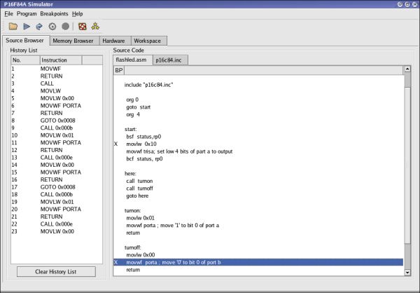
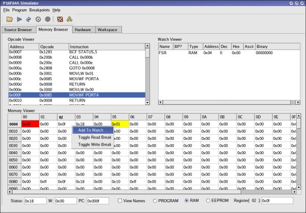
Microprocessor Simulator on Linux [ Screenshot tour ]

Microprocessor Simulator on Linux

Features:

  • Easy-to-use graphical interface.
  • You may use your regular IBM PC to run simulation software that controls real hardware in real time, through the parallel port on Linux.
  • An open source (for non-commercial products)and easy-to-use IDE that uses the Qt graphics library to help users build effective designs.


Download the software on sourceforge.net @ Microprocessor Simulator on Linux.

[Source ]

Feb 25, 2009

Embedded Linux/Microcontroller Project


The Linux/Microcontroller project is a port of Linux to systems without a Memory Management Unit (MMU). The Linux/Microcontroller Project has grown both in brand recognition and coverage of processor architectures. Today's uClinux as an operating system includes Linux kernel releases for 2.0 2.4 and 2.6 as well as a collection of user applications, libraries and tool chains.

For more: uCLinux


Jan 8, 2009

Microcontroller and Programmer Kit for Beginner buy in india

Generally a beginner require a programming kit with following features.

General purpose kit with all ports available to you,
some interfacing device interfaces ,like stepper motor, LCD, LED, key/keypad, relay's.
Some extra's like ADC, DAC.
they may choose any microcontroller with 8051 core , depending upon there RAM, flash requirement but 89C51RD2 is one of the good microcontroller.

In India you can buy microcontroller kit online at www.emblitz.com
If you have credit card you can shop online and deliver it to your house.

The price details are as follows
Embedded Starter Kit is for Rs. 3970 only
Embedded ARM Starter Kit Rs. 5980 only

More details can be found in there web site

Dec 22, 2008

Our Blog statistics

We have compiled and published over hundred assembly language programs and tutorials over the past one year now on this blog and we would like to thank our blog subscribers and our loyal visitors for the support, feedback and response.

We intend to bring you more tutorials and source codes related to microprocessors and microcontrollers in the future. Following is the summary of the traffic details our blog received


If you have any feedback, queries or comments you can reach us at kpac.ltd [at] gmail [dot] com

Dec 17, 2008

program to find the sum of squares of n numbers

program to find the sum of squares of n numbers

initially we load the si and di registers and we move contents of si to that of cl and then we continue to increment si and move si to al and multiply the current result with al. Then we move contents of si to that of bl and we multiply bl and add the result in ax to that of di.

the code can be analyzed as follows

mov si,2000
mov di,4000
mov cl, [si]
inc si
mov dx,0
l1 mov ah,00
mov l,[si]
add dx,ax
inc si
loop l1
Mov [di],dx
int a5