Google

Jan 28, 2008

Temperature Control system using 8086

AIM:-

To develop Temperature Control system using 8086

APPARATUS:-

Microprocessor trainer kit, Temperature controller kit, power supply, data cable etc

THEORY:-

Temperature control system involved interfacing successive approximation ADC and typical method of measuring and controlling the temperature using microprocessor. ADC is among the most widely used devices for data acquisition. A digital computer uses binary values, but in physical world everything is analog, temperature, pressure, humidity, and velocity are few examples of physical quantities that we seal with every day.

Temperature measurement is of great importance in industry as most of the processes are temperature dependent. A number of devices and schemes have been used over the years, for the measurement of temperature. Typical sensors include devices like thermocouples, thermostats, RTD’s and semiconductor sensor.

This system uses semiconductor sensor AD590 to monitor the temperature of water bath. The AD590 is basically a PTAT (proportional to absolute temperature) current regulator. It generates a current O/P of 1µA/K above absolute zero temperature that is -2730C. Thus at 00C the current O/P will be 273µA and 250 if will be 298µA and 373mV at 1000. This O/p is buffered through an OPAMP having a gain of 10. To enable easy equivalence between the transducers O/P in volts and the measured temperature a calibration procedure needs to be done.

WORKING:-

8255 is interfaced with 8086 in I/O mapped I/O. port A (PA0-PA7) as input port is connect to data lines of ADC, PB0, PB1, PB2 lines of port B for channel selection, PC2 connected to Start of conversion (SOC) and PC3 to O/P enable. Channel 1 of ADC is used to input analog signal, Channel 0 of ADC for temperature controller.

ADC will give binary equivalent of the I/P voltage. Input will vary from 0 to 5V (0 to 100 degree C) and the ADC O/P varies from 00-FFH. So 5V/100 i.e. 5000mvs/100 gives 50mvs/0C. And the counts for indication of temperature are taken as 2.5 (256/100) per degree C.

AC supply to the external heating element is controlled through the onboard Relay, based on the set value. When the temperature of the heating element (which is sensed by AD590, AD590 output is analog which is converted to digital by ADC) is less than the set value (reference value) heating element will be switched ON and when temperature crosses the set temperature AC supply is turned OFF.


MODEL SMALL
.STACK 100
.DATA
START:
PORTA EQU FFC0H ; PORTA address
PORTB EQU FFC2H ; PORTB address
PORTC EQU FFC4H ; PORTC address
CTL EQU FFC6H ; Control port address
CTL_BYTE EQU 98H ; 8255 control reg.
CLEAR_DISPLAY EQU F800:4BB1H
DWAD EQU F800:4BB1H
DBDTA EQU F800:4F1F
DEC_TEMP DB 0
SET_TEMP DB 0
ADC_VAL DB 0
COUNT DB 0
PRE_TEMP DB 0
.CODE
ADC TABLE:

DB 00H,03H,05H,08H,0aH,0dH,0fH,11H,14H,16H


DB 19H,1cH,1eH,21H,24H,27H,2aH,2cH,2eH,32H

DB 34H,36H,39H,3cH,3fH,42H,45H,48H,4aH,4cH

DB 4eH,50H,52H,54H,56H,58H,5bH,61H,64H,67H

DB 6aH,6dH,70H,72H,74H,77H,7aH,7dH,7fH,82H

DB a0H,a2H,a5H,a8H,aaH,aDH,afH,b0H,b3H,b6H

DB b9H,bcH,bfH,c1H,c4H,c6H,c9H,ccH,cfH,d0H

DB d2H,d5H,d7H,daH,dcH,dfH,e0H,e2H,e5H,e7H

DB e9H,ebH,eeH,f1H,f4H,f6H,f9H,fcH,ffH

START:
MOV AL,CTL_BYTE ; 8255
MOV DX,CTL ; PORTC (lower) as output
OUT DX,AL ; PORTA as input
MOV AL,DEC_TEMP
CALL DEC_HEX
MOV SET_TEMP,AL
MOV AL,DEC_TEMP
MOV AH,00
MOV SI,AX
CALL FAR DWAD
MOV DX,CTL
MOV AL,02
OUT DX,AL
MOV AL,00
OUT DX,AL
MOV CX,70
L0:
LOOP L0
BACK:
MOV COUNT,0
CALL ADC
CALL DISP_TEMP
CALL TEMP_CONTL
JMP BACK
DISP_TEMP:
MOV AL,ADC_VAL
MOV SI,OFFSET ADC_TABLE
AGAIN:
CMP AL,[SI]
JC FOUND
JE FOUND
INC SI
INC COUNT
JMP AGAIN
FOUND:
MOV AL,COUNT
CALL HEX_DEC
MOV AH,0
MOV SI,AX
CALL FAR DBDTA
RET
TEMP_CONTL:
MOV AL,COUNT
CMP AL,SET_TEMP
JC TURN_ON_RELAY
RELAY_OFF:
MOV DX,PORTB
MOV AL,0FFH
OUT DX,AL
MOV DL,20H
HERE1:
MOV CX,FFFFH
HERE:
LOOP HERE
DEC DL
JNZ HERE1
RET
TURN_ON_RELAY:
MOV DX,PORTB
MOV AL,00H
OUT DX,AL
CONTINUE:
MOV CX,FFFFH
L22:
LOOP L22
RET
ADC:
MOV DX,CTL
MOV AL,01
OUT DX,AL
MOV CX,70
L10:
LOOP L10
MOV AL,00
OUT DX,AL
L1:
MOV DX,PORTC
IN AL,DX
AND AL,80H
CMP AL,80H
JNZ L1
MOV DX,PORTA
IN AL,DX
MOV ADC_VAL,AL
RET
HEX_DEC:
MOV AH,00H
MOV CL,0AH
DIV CL
MOV CL,04H
ROL AL,CL
AND AL,F0H
OR AL,AH
RET
DEC_HEX:
MOV BL,AL
AND BL,0FH
AND AL,F0H
MOV CL,04
ROR AL,CL
MOV CL,0AH
MUL CL
ADD AL,BL
RET
END START

PROCEDURE:-

1. Connect power supply 5V & GND to both microprocessor trainer kit & temperature controller interfacing kit.

2. Connect data bus between microprocessor trainer kit & temperature controller interfacing kit.

3. Enter the program to read temperature of the water bath from ADC at 0000:4000.

4. Execute the program by typing GO 0000:4000 enter.

5. Enter the reference temperature value, when temperature of water bath exceeds reference value then power supply to water bath is switched OFF.


You might be also interested in:

:: Traffic light control system using 8086
:: Assembly Language Program to serve NMI
:: Interfacing Stepper Motor to 8086 using 8255
Jan 23, 2008

common intreview questions on 8086

1) what is segmentation?
2) how many bit processor does 8086?
3) how many address lines in 8086
4) how many data lines in 8086?
5) multiplexed lines in 8086?
6) over flow flag, interrupt flag ,direction flag, trap flag?
7) role of pointers ?
8) how 16 bit processor generates 20 bit addresses
9) instructions set of 8086
10) timing diagram of 8086
11) min/max mode working of 8086?
12) pin difference in min/max mode
13) interrupt structure in 8086?
14) how an interrupt is acknowledged?
15) how the cs:ip is working during interrupt
16) new cs:ip during interrupt
17) how the even odd address are assigned through 8086?


the remaning questions can be found at : here
You might be also interested in:
:: Assembly Language Programs for Multiplication and Division
:: Assembly Language Programs on array of Hexadecimal numbers

Jan 22, 2008

Interfacing Stepper Motor to 8086 using 8255

To Interface Stepper Motor to 8086 using 8255 and write Assembly Language Program to rotate Stepper Motor in Clockwise & Anticlockwise direction.

APPARATUS:-
Microprocessor trainer kit, ADC kit, power supply, data cable etc

THEORY:-
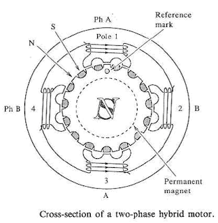
Stepper motor is a device used to obtain an accurate position control of rotating shafts. A stepper motor employs rotation of its shaft in terms of steps, rather than continuous rotation as in case of AC or DC motor. To rotate the shaft of the stepper motor, a sequence of pulses is needed to be applied to the windings of the stepper motor, in proper sequence. The numbers of pulses required for complete rotation of the shaft of the stepper motor are equal to the number of internal teeth on its rotor. The stator teeth and the rotor teeth lock with each other to fix a position of the shaft. With a pulse applied to the winding input, the rotor rotates by one teeth position or an angle x. the angle x may be calculated as.
x = 3600 / no. of rotor teeth
After the rotation of the shaft through angle x, the rotor locks it self with the next tooth in the sequence on the internal surface of the stator. The typical schematic of a typical stepper motor with four windings is as shown below.


The stepper motors have been designed to work with digital circuits. Binary level pulses of 0-5V are required at its winding inputs to obtain the rotation of the shafts. The sequence of the pulses can be decided, depending upon the required motion of the shaft. By suitable sequence of the pulses the motor can be used in three modes of operation.


  • One phase ON (medium torque)
  • Two phase ON (high torque)
  • Half stepping (low torque)


WORKING:-
8255 is interfaced with 8086 in I/O mapped I/O. port C (PC0, PC1, PC2, PC3) is used to give pulse sequence to stepper motor. The 8255 provides very less current which will not be able to drive stepper motor coils so each of the winding of a stepper motor needs to be interfaced using high speed switching Darlington transistors with max 1A, 80V rating with heat sink, with the output port of 8255. Output the sequence in correct order to have the desired direction to rotate the motor.


Assembly Language Program to rotate Stepper Motor in Clockwise direction

MODEL SMALL
.STACK 100
.DATA
PORTA EQU FFC0H ; PORTA ADDRESS
PORTB EQU FFC2H ; PORTB ADDRESS
PORTC EQU FFC4H ; PORTC ADDRESS
CWR EQU FFC6H ; CONTROL PORT ADDRESS
PHASEC EQU 03H
PHASEB EQU 06H ; SEQUENCE IN SERIES TO ROTATE MOTOR
PHASED EQU 0CH ; IN CLOCKWISE DIRECTION
PHASEA EQU 09H
.CODE
START:
MOV AL,@DATA
MOV DX,CTL
OUT DX,AL
AGAIN:
MOV AL,PHASEC
MOV DX,PORTC
OUT DX,AL
MOV CX,0FFFFH
UP:
LOOP UP

MOV AL,PHASEB
MOV DX,PORTC
OUT DX,AL
MOV CX,0FFFFH
UP1:
LOOP UP1

MOV AL,PHASED
MOV DX,PORTC
OUT DX,AL
MOV CX,0FFFFH
UP2:
LOOP UP2

MOV AL,PHASEA
MOV DX,PORTC
OUT DX,AL
MOV CX,0FFFFH

UP3:
LOOP UP3
JMP AGAIN ; REPEATE OUTPUT SEQUENCE
INT 03H
END START


Assembly Language Program to rotate Stepper Motor in Anticlockwise direction
MODEL SMALL
.STACK 100
.DATA
PORTA EQU FFC0H ; PORTA ADDRESS
PORTB EQU FFC2H ; PORTB ADDRESS
PORTC EQU FFC4H ; PORTC ADDRESS
CWR EQU FFC6H ; CONTROL PORT ADDRESS
PHASEC EQU 03H
PHASEA EQU 09H ; SEQUENCE IN SERIES TO ROTATE MOTOR
PHASED EQU 0CH ; IN ANTICLOCKWISE DIRECTION
PHASEB EQU 06H

.CODE
START:
MOV AL,@DATA
MOV DX,CTL
OUT DX,AL
AGAIN:
MOV AL,PHASEC
MOV DX,PORTC
OUT DX,AL
MOV CX,0FFFFH
UP:
LOOP UP

MOV AL,PHASEA
MOV DX,PORTC
OUT DX,AL
MOV CX,0FFFFH
UP1:
LOOP UP1

MOV AL,PHASED
MOV DX,PORTC
OUT DX,AL
MOV CX,0FFFFH
UP2:
LOOP UP2

MOV AL,PHASEB
MOV DX,PORTC
OUT DX,AL
MOV CX,0FFFFH
UP3:
LOOP UP3
JMP AGAIN ; REPEATE OUTPUT SEQUENCE
INT 03H
END START


PROCEDURE:-
1. Connect power supply 5V & GND to both microprocessor trainer kit & Stepper motor interfacing kit.
2. Connect data bus between microprocessor trainer kit & Stepper motor interfacing kit.
3. Enter the program to rotate Stepper motor in clockwise & anticlockwise.
4. Execute the program by typing GO E000:00C0 ENTER for clockwise, GO E000:0030 ENTER for anticlockwise.
5. Observe the rotation of stepper motor.


You might be also interested in:
:: Temperature Control system using 8086
:: Traffic light control system using 8086
:: Assembly Language Program to serve NMI

Jan 17, 2008

Interfacing Digital-To-Analog converter to 8086 using 8255


  1. Assembly Language Program to generate Square Wave
  2. Assembly Language Program to generate Ramp Wave
  3. Assembly Language Program to generate Triangular Wave
  4. Assembly Language Program to generate Staircase Wave


AIM:-
To Interface Digital -to-Analog converter to 8086 using 8255 and write Assembly Language Program to generate Square Wave, Ramp Wave, Triangular Wave & Staircase Wave form.

APPARATUS:-
Microprocessor trainer kit, ADC kit, power supply, data cable, CRO etc

THEORY:-
The DAC 0800 is a monolithic 8 bit high speed current output digital to analog converters featuring setting time of 100nSEC. It also features high compliance complementary current outputs to allow differential output voltage of 20 Vp-p with simple resistor load and it can be operated both in unipolar and bipolar mode.

FEATURES:-
  1. Fast setting output current 100nS
  2. Full scale error +/- 1 LSB
  3. Complementary current outputs
  4. easy interface to all microprocessor
  5. Wide power supply range +/- 4.5 to +/- 18V
  6. low power consumption

WORKING:-
When chip select of DAC is enabled then DAC will convert digital input value given through portliness PB0-PB7 to analog value. The analog output from DAC is a current quantity. This current is converted to voltage using OPAMP based current-to-voltage converter. The voltage outputs (+/- 5V for bipolar 0 to 5V for unipolar mode) of OPAMP are connected to CRO to see the wave form.


; RAMP WAVE GENERATOR with 8086 using 8255
MODEL SMALL
.STACK 100
.DATA
CONTROL EQU 0FFC6H ; Control port address for 8255
PORTA EQU 0FFC0H ; Port A address for 8255
PORTB EQU 0FFC2H ; Port B address for 8255
PORTC EQU 0FFC4H ; Port C address for 8255
.CODE
START:
MOV AX,@DATA ;Initialize Data segment
MOV DS,AX
MOV DX,CONTROL
MOV AL,80H ;Initialize all ports as output
OUT DX,AL ;Ports

MOV BL,FFH ;Take FFH in BL analog equivalent to 5V
RAMP : MOV DX,PORTB
MOV AL,BL ;Copy to AL
OUT DX,AL ;And output it on the port
DEC BL ; To generate ramp wave this 5V is continuously decreased till 0V
JNZ RAMP ; Jump to RAMP if not 0
MOV BL,FFH ; To generate same wave this procedure is repeated
JMP RAMP
INT 03H
END START


;SQUARE WAVE GENERATOR with 8086 using 8255
MODEL SMALL
.STACK 100
.DATA
CONTROL EQU 0FFC6H ; Control port address for 8255
PORTA EQU 0FFC0H ; Port A address for 8255
PORTB EQU 0FFC2H ; Port B address for 8255
PORTC EQU 0FFC4H ; Port C address for 8255

.CODE
START:
MOV DX,CONTROL
MOV AL,80H ; Initialize all ports as output
OUT DX,AL ; Ports
UP: MOV DX,PORTB
MOV AL,00H ;Output 00 for 0V level
CALL OUTPUT
MOV AL,0FFH ;Output FF for 5V level
CALL OUTPUT
JMP UP
OUTPUT:
OUT DX,AL
CALL DELAY
INT 21H

DELAY:
MOV CX,0FFH ; To vary through frequency alter the delay count
LUP1 LOOP LUP1
INT 21H

END START


;TRIANGULAR WAVE GENERATOR with 8086 using 8255

MODEL SMALL
.STACK 100
.DATA
CONTROL EQU 0FFC6H ; Control port address for 8255
PORTA EQU 0FFC0H ; Port A address for 8255
PORTB EQU 0FFC2H ; Port B address for 8255
PORTC EQU 0FFC4H ; Port C address for 8255

.CODE
START:
MOV DX,CONTROL
MOV AL,80H ; Initialize all ports as output
OUT DX,AL ; Ports

BEGIN:
MOV DX,PORTB
MOV AL,00H ; Output 00 for 0V level
UP: CALL OUTPUT
INC AL ; To raise wave from 0V to 5V increment AL
CMP AL,00H
JNZ UP ; Jump UP till rising edge is reached i.e. 5V

MOV AL,0FFH
UP1: CALL OUTPUT
DEC AL ; To fall wave from 5V to 0V decrement AL
CMP AL,0FFH
JNZ UP1 ; Jump UP till falling edge is reached i.e. 0V
JMP BEGIN

OUTPUT:
OUT DX,AL
CALL DELAY
INT 21H

DELAY:
MOV CX,07H ;To vary the frequency alter the delay count
LUP1:LOOP LUP1
INT 21H

END START


;STAIRCASE WAVEFORM GENERATOR with 8086 using 8255

MODEL SMALL
.STACK 100
.DATA

CONTROL EQU 0FFC6H ; Control port address for 8255
PORTA EQU 0FFC0H ; Port A address for 8255
PORTB EQU 0FFC2H ; Port B address for 8255
PORTC EQU 0FFC4H ; Port C address for 8255

.CODE
START:
MOV DX,CONTROL
MOV AL,80H ;Initialize all ports as output
OUT DX,AL ;Ports

UP: MOV DX,PORTB
MOV AL,00H ;Output 00 for 0V level
CALL OUTPUT ; And wait for some time
MOV AL,0FFH ;Output FF for 5V level
CALL OUTPUT ; And wait for some time
MOV AL,07FH ;Output 7F for 2.5V level
CALL OUTPUT ; And wait for some time
JMP UP

OUTPUT: OUT DX,AL
MOV CX,FFH
DELAY: LOOP DELAY ; To add DELAY
INT 03H
END START

PROCEDURE:-
  1. Connect power supply 5V & GND to both microprocessor trainer kit & DAC interfacing kit.
  2. Connect data bus between microprocessor trainer kit & DAC interfacing kit.
  3. Enter the program to generate Ramp, Square, Triangular & Staircase Wave.
  4. Execute the program by typing GO E000:4770 ENTER for Ramp, GO E000:03A0 ENTER for Square, GO E000:0410 ENTER for Triangular, GO E000:4890 ENTER for Staircase.
  5. Observe the wave forms on CRO.
You might be also interested in:
:: Temperature Control system using 8086
:: Traffic light control system using 8086
:: Assembly Language Program to serve NMI

Jan 10, 2008

Analog-to-Digital converter with 8086 using 8255

AIM:- To Interface Analog-to-Digital converter to 8086 using 8255 and write Assembly Language Program to read Digital value from ADC.

APPARATUS:-
Microprocessor trainer kit, ADC kit, power supply, data cable etc

THEORY:

ANALOG TO DIGITAL CONVERTER (0809):-
The ADC-0809 data acquisition component is a monolithic CMOS device with an 8-bit analog to digital converter, 8 channel multiplexed control logic. The 8 bit A/D converter uses successive approximation as the converter technique. The converter features a high impedance chopper stabilized comparator, a 256R voltage divider with analog switch free and a successive approximation register. The 8 channel multiplexed can directly access any of 8 single ended analog signal.

FEATURES:-
  1. Resolution 8 bits
  2. Conversion time 100 micro sec.
  3. Single supply 5V
  4. 8 channel multiplexed with latched control logic
  5. easy interface to all microprocessor
  6. 0 to 5V analog input voltage range with single 5V supply
  7. low power consumption 15mW
  8. latched tristate output

WORKING:-
ADC interface consists of a NAND gate oscillator witch feeds 50 KHz as the input clock to ADC, input to channel is given through terminal blocks provided on the card. Channel selection is done using port lines PC0, PC1 & PC2, START OF CONVERSION and ALE is controlled by port line PC7. Converted digital output is read by ADC through PORTA lines by enabling OE. OE line is connected to port line PC6.
In this method of interfacing microprocessor is continuously monitoring EOC line (which is connected to port line PA7). When this goes high, make OE (PC6) high & then low, this will put the digital equivalent of analog voltage of the given channel on data lines of ADC. Read the digital data through port lines PA0 to PA7 and display the same data.


ASSEMBLY LANGUAGE PROGRAM:-
MODEL SMALL
.STACK 100
.DATA
CONTROL EQU FFC6H ; Control port address for 8255
PORTA EQU FFC0H ; Port A address for 8255
PORTB EQU FFC2H ; Port B address for 8255
PORTC EQU FFC4H ; Port C address for 8255
CHANNEL EQU 07H

.CODE
START:
MOV AL,90H ;CONTROL WORD FOR 8255
MOV DX,CONTROL ;TO INITIALIZE PORTA AS INPUT, PORTB AS OUTPUT
OUT DX,AL ;PORTC AS OUTPUT PORT
MOV AL,CHANNEL ; OUTPUT CHANNEL NUMBER IS PLACED ON
MOV DX,PORTC ; PC0, PC1, PC2 LINES OF 8255 WHICH ARE CONNECTED
OUT DX,AL ; TO ADC TO SELECT RESPECTIVE CHANNEL OF ADC TO
; TAKE ANALOG INPUT
MOV AL,0FH ; AS PC7 OF 8255 IS CONNECTED TO START OF
MOV DX,CONTROL ; CONVERSION (SOC) OF ADC SO TO START CONVERSION
OUT DX,AL ; PC7 IS SET HIGH
MOV CX,3FFFH
DELAY: LOOP DELAY

MOV AL,0EH ; RESET PC7
MOV DX,CONTROL
OUT DX,AL

MOV AL,0CH ; AS PC6 IS CONNECTED TO OE i.e. OUTPUT ENABLE OF
OUT DX,AL ; ADC SO TO DISABLE OE AND AND TO CHECK EOC
; (CONNECTED TO PA7) RESET PC6
UP: MOV DX,PORTA
IN AL,DX ; CHECK FOR EOC BY READING PORTA
AND AL,80H ; MASK PC7 BIT
CMP AL,80H ; COMPARE PC7 BIT WITH 1
JNZ UP ; IF EOC THEN READ DIGITAL VALUE FROM ADC

MOV AL,0DH
OUT DX,CONTROL ; TO CONFIGURE ADC TO OUTPUT THE DIGITAL DATA
OUT DX,AL ; SO SET OE (PC6) TO READ VALUE

MOV DX,PORTA ; READ DIGITAL DATA FROM PORTA
IN AL,DX ; DIGITAL DATA IS IN AL
INT 03H

END START


PROCEDURE:-
1. Connect power supply 5V & GND to both microprocessor trainer kit & ADC interfacing kit.
2. Connect data bus between microprocessor trainer kit & ADC interfacing kit.
3. Enter the program to read digital data from ADC.
4. Execute the program by typing GO E000:4610 ENTER.
5. “ENTER THE CHANNEL NUMBER “, will be displayed on screen.
6. Now enter the channel number and apply the analog input to respective channel.
7. Equivalent digital output is displayed on screen.

Analog input Digital output
1V 33H
2V 66H

3V 99H
4V CCH
5V FFH

You might be also interested in:
:: Temperature Control system using 8086
:: Traffic light control system using 8086
:: Assembly Language Program to serve NMI


Jan 5, 2008

Find Square Root of a hexadecimal number in assembly language

To write 8086 Assembly Language Program to Find Square Root of a hexadecimal number.

Answer:

; SQUARE ROOT OF A NUMBER
MODEL SMALL
.STACK 100
.DATA ; Data segment starts
NUM1 DW 0019H ; Initialize num1 to 0019
SQRT DW 01 DUP (?) ; Reserve 1 word of uninitialised data space to offset sqrt
.CODE ; Code segment starts
START:
MOV AX,@DATA ;Initialize data segment
MOV DS,AX
MOV AX,NUM1 ;Move the number(num1) to AX
XOR BX,BX ;XOR is performed and result is stored in BX
MOV BX,0001H ;Initialize BX to 0001H
MOV CX,0001H ;Initialize CX to 0001H
LOOP1: SUB AX,BX ;AX=AX-BX
JZ LOOP2 ; If zero flag is zero jump to loop2
INC CX ; Increment CX by 1
ADD BX,0002H ;BX=BX+0002H
JMP LOOP1 ; Jump to loop1
INC CX ; Increment CX by 1
LOOP2: MOV SQRT,CX ; Store result
INT 03H ; halt
END START


INPUT:
NUM1 = 0019 H (25 IN DECIMAL)
NUM1 = 0090 H (144 IN DECIMAL)
OUTPUT:
RES = 0005H
RES = 000CH


_________________________________________________________________

AIM: To write 8086 Assembly Language Program to Find Number of one’s & zero’s in a hexadecimal number.


Answer:

MODEL SMALL
.STACK 100
.DATA ; Data segment starts
NUM DW 0F0F0H ; Initialize num to F0F0 H
ONES DB ? ; Reserve 1 byte for storing number of zeros
ZEROS DB ? ; Reserve 1 byte for storing number of ones
.CODE ; Code segment starts
START:
MOV AX,@DATA ;Initialize DS
MOV DS,AX
MOV CL,10H ;Initialize CL to 10H
MOV BX,0000H ;Initialize BX to 0000H
MOV AX,NUM ;Move contents of num to AX
UP:
SHL AX,1 ;Shift the contents of AX left once
JC AHEAD ; If CF=1 jump to label ahead
INC BL ; Increment BL by 1
JMP DOWN ; Jump to the label down
AHEAD:
INC BH ; Increment BH by 1
DOWN:
DEC CL ; Decrement CL by 1
JNZ UP ; If zero flag is not 0 jump to label up
MOV ONES,BH ;Move contents of BH to ones
MOV ZEROS,BL ;Move contents of BL to zeros
INT 03H ; Halt
END START


INPUT:
NUM = 0F0F0 H (0000 1111 0000 1111 0000 b)

OUTPUT:
ONES = 08 H
ZEROS = 08 H


____________________________________________________________________


AIM: To write 8086 Assembly Language Program to Find Factorial of a hexadecimal number.

Answer:

; This ALP will find factorial from 01 H to 08 H

MODEL SMALL
.STACK 100
.DATA ; Data segment starts
NUM DW ?
RES DB 1H
FACT DW ?
.CODE ; Code segment starts
START:
MOV AX,@DATA ; Initialize DS
MOV DS,AX
MOV AH,01 ; Move 01 to AH to take input at runtime
INT 21H ; Dos interrupt
AND AX,000FH ; Logical AND of AX,000f and stores in AX
MOV NUM,AL ; Move contents of AL to val1
MOV CX,AL ; Move contents of AL to CL
MOV AX,RES ; Move contents of res(1) to AX
M:
MUL CX ; AX = AX*CX
LOOP M ; Decrements CX by 1 continues multiplication until CX is 0
MOV FACT,AX ; Value of AX is moved to fact
INT 03H ; Halt
END START


INPUT
8 (DURING RUNTIME)
OUTPUT:
FACT = D980 H


_________________________________________________________________


AIM: To write 8086 Assembly Language Program to Convert BCD to 7-Segment display using lookup table.

Answer:

MODEL SMALL
.STACK 100
.DATA ; Data segment starts and defines array A having
; Equivalent 7 segment codes

A DB 3FH, 06H, 5BH, 4FH, 66H, 6DH, 7DH, 07H, 7FH, 6FH

C EQU 06 ; BCD number which is to be converted
7SEG DB ? ; 7 segment code
.CODE ; Code segment starts
START:
MOV AX,@DATA ; Initialize data segment
MOV DS,AX
MOV BX,OFFSET A ; Moves the starting address of A to BX
MOV AL,C ; Move C value to AL register
XLAT ; It i'll add [BX+AL] i.e. 0000 + 06 = 0006 H
MOV 7SEG,AL ; Store the result
INT 03H ; Halt
END START


INPUT:
C = 06 H
OUTPUT:
AL = 7D H

You might be also interested in:
:: Traffic light control system using 8086
:: Assembly Language Program to serve NMI
:: MASM 611 SOFTWARE
:: bit reversal and sorting programs

Jan 2, 2008

bit reversal and sorting programs [ assembly language ]

bit reversal and sorting programs [ assembly language ]

1)bit reversal(FOR 16 BIT)


MOV CX,0010 ;count=16 (16 bit)
MOV AX,[1100];16 bit input
MOV BX,0000;result
L1:SHL AX,01;each bit of input inserted into BX in opp direc
RCR BX,01
LOOP L1
MOV [2000],BX
HLT


2)program to sort an array in acending order
clc
mov cx,[3000h]
dec cx
l1: push cx
mov si,2000
l2:mov ax,[si]
mov bx,[si+2]
cmp bx,ax
jbe l3
xchg ax,bx
mov [si],ax
mov [si+2],bx
l3:inc si
inc si
loop l2
pop cx
loop l1
hlt

just replace 'jbe' by 'jae' to get the descending order program code...

You might be also interested in:
:: Interfacing Analog-to-Digital converter to 8086 using 8255
:: Interfacing Digital-To-Analog converter to 8086 using 8255
:: Temperature Control system using 8086
:: Traffic light control system using 8086

Jan 1, 2008

Assembly Language Programs to compute an expression

AIM: To write 8086 Assembly Language Program to compute Z = (A + B) × C × (D ÷ E).

Program

MODEL SMALL

.STACK 100

.DATA ; Data segment starts

A DB 56H ; Initialize A to 56H

B DB 78H ; Initialize B to 78H

C DB 05H ; Initialize C to 05H

D DB 0ACH ; Initialize D to ACH

E DB 04H ; Initialize E to 04H

Z DW ? ; Declare Z


.CODE ; Code segment starts

START:

MOV AX,@DATA ;Initialize DS

MOV DS,AX

MOV AL,A ;Move contents of A to AL

MOV BL,B ;Move contents of B to BL

ADD AL,BL ;AL = AL + BL

MOV CL,C ;Move contents of C to CL

MUL CL ; AL = AL×CL

MOV BX,AX ;Move contents of AX to BX

MOV AX,0000 ;Move 0000 to AX

MOV AL,D ;Move contents of D to AL

MOV CL,E ;Move contents of E to CL

DIV CL ; AL = AL ÷ CL

MUL BX ; AX = AX×BX

MOV Z[SI+2],AX ;Move contents of Z to AX

MOV Z[SI],DX ;Move contents of Z1 to DX

INT 03H ; Halt

END START


INPUT:

A = 56H

B =78H

C = 05H

D = 0ACH

E = 04H

OUTPUT:
Z = 0000 0AD02 H

AIM: To write 8086 Assembly Language Program to compute Z = ∑ Xi × Yi.

MODEL SMALL

.STACK 100

.DATA ; Data segment starts

X DB 1H, 2H, 3H ; Declare array of 3bytes named X

Y DB 4H, 5H, 6H ; Declare array of 3bytes named Y

Z DW ? ; Reserve 1word by name Z

.CODE ; Code segment starts

START:

MOV AX,@DATA ; Initialize DS

MOV DS,AX

MOV DX,0000H ;Initialize DX to 0000h

MOV BX,0000H ;Initialize BX to 0000h

MOV SI,0000H ;Initialize SI to 0000h

MOV CL,03H ;Initialize CL to 03h

UP:

MOV AL,X[BX] ;Move the elements of X to AL

MUL BYTE PTR Y[SI] ;Multiply AL with the contents of Y

ADD DX,AX ;DX=DX+AX+CF

INC BX ; Increment BX by 1

INC SI ; Increment SI by 1

DEC CL ; Decrement CL by 1

JNZ UP ; If zero flag is not zero jump to label up

MOV Z,DX ;Move the contents of DX to Z

INT 03H ; Halt

END START

INPUT:

X =1H, 2H, 3H

Y = 4H, 5H, 6H


OUTPUT:

Z = 0020 H


AIM: To write 8086 Assembly Language Program to compute Z = ∑ Xi2.

MODEL SMALL

.STACK 100

.DATA ; Data segment starts

X DB 0FFH, 0FFH, 0FFH ; Initialize X with 3bytes

Z DW ? ; Initialize Z

.CODE ; Code segment starts

START:

MOV AX,@DATA ;Initialize AX

MOV DS,AX

MOV DX,0000H ;Initialize DX to 0000h

MOV BX,0000H ;Initialize BX to 0000h

MOV CH,03H ;Initialize CH to 03h

MOV CL,00H ;Initialize CL to 00h

MOV DX,0000H ;Initialize DX to 0000h

MOV SI,0000H ;Initialize SI to 0000h

UP: MOV AL,X[BX] ;Move contents of X[BX] to AL

MUL BYTE PTR X[BX] ;Multiply AL with contents of X[BX]

ADD DX,AX ;DX=DX+AX

ADC CL,00H ;CL=CL+00+CF

INC BX ; Increment BX by 1

DEC CH ; Decrement CH by 1

JNZ UP ; If zero flag is not zero jump to up

MOV Z[SI],CX ;Move contents of CX to Z[SI]

MOV Z[SI+2],DX ;Move contents of DX to Z[SI+2]

INT 03H ; Halt

END START


INPUT:

Z = FF2 + FF2 + FF2 = 2FA03 H

X =FFH, FFH, FFH

OUTPUT:

Z = 0002 FA03 H

AIM: To write 8086 Assembly Language Program to compute Z = ∑ Xi3.

MODEL SMALL

.STACK 100

.DATA ; Data segment starts

A DB 0FFH, 0FFH, 0FFH ; Initialize an array A

Z DW ?

.CODE ; Code segment starts

START:

MOV AX,@DATA ; Initialize the data segment

MOV DS,AX

MOV BX,0000H ; Initialize the BX register

MOV CX,03H ; CX register is decremented whenever loop instruction executes

MOV SI,00H ; Initialize SI & DI

MOV DI,0000H

UP: XOR AX,AX ; Clear AX register

MOV AL,A[SI] ;Move the element in array A pointed by SI to AL

MOV BX,AX ;Move AX register to BX

MUL AX ; Multiplies AX with AX

MUL BX ; Multiplies BX with AX and stores the result in DX:AX

ADD Z[DI+2],AX ; Adds lower 16 bits of z with AX

ADC Z[DI],DX ; Adds higher 16 bits of z with DX

ADD SI,01 ; Increment SI by 1

LOOP UP ; Goes up until CX becomes zero

INT 03H ; Halt

END START

INPUT:

Z = FF3 + FF3 + FF3 = 02F7 08FD H

ARRAY OF 3 NO'S (FFH, FFH, FFH)

OUTPUT:

Z = 02F7 08FD H

You might be also interested in:

:: MASM 611 SOFTWARE

:: Traffic light control system using 8086

:: Interfacing Stepper Motor to 8086 using 8255