Google

Feb 27, 2008

Assembly Language Source Codes

Here is the list of programs in assembly language with complete source code is provided

Assembler Source Code for emu8086 microprocessor emulator and compatible assemblers (16 bit) simply copy these codes and past them on your editor

http://www.emu8086.com/dr/asm2html/assembler_source_code/

it contains list of programs like
  • Input 8 bit binary number and print out its decimal equivalent.
  • This is a very basic example of a tiny OS. Your own Operating System that runs from floppy drive - easy!
  • This example shows how to add huge unpacked BCD numbers
  • Calculate the sum of elements in V1 array, store result in V2.
  • How CMP instruction sets the flags.
  • See how to operate with Octal, Binary and Decimal values.
  • Learn how to set and get file attributes, in other words how to make file Read Only or Hidden.
  • This is an example of AAS instruction, it is used to subtract huge BCD numbers.
  • This sample gets two numbers from the user, calculates the sum of these numbers, and prints it out.
  • This sample shows how to use CMPSW instruction to compare strings.
  • Make your own interrupts - Custom_Interrupt.asm
  • Encryption in Assembly Language
  • This sample gets the number from the user, and calculates factorial for it. Supported input from 0 to 8 inclusive!
  • Call a procedure from another segment or interrupt.
  • This program calculates linear equation: ax + b = 0 The result is printed with floating point.
  • This example prints out The easiest and the fastest way to print "Hello World!" using DOS INT 21h (still works under Windows XP in Dos prompt).
  • This example converts 2 digit Hex value into numeric value and decimal string representation (so that it can be easily printed if required).
  • Keyboard example - keybrd.asm
  • A very handy code that can be assembled into a very tiny utility to make floppy boot records and tiny operating systems.
  • This sample shows the use of input and output string functions of emu8086.inc
  • This sample shows how to use SCASW instruction to find a WORD (2 bytes).
You might be also interested in:
:: Temperature Control system using 8086
:: Traffic light control system using 8086
:: Assembly Language Program to serve NMI

Feb 19, 2008

Assembly Language Program to be executed when NMI is generated

Assembly Language Program to be executed when NMI is generated

AIM:To write Assembly Language Program to be executed when NMI is generated

APPARATUS:-
Microprocessor trainer kit & power supply.

NON MASKABLE INTERRUPT (NMI)

NMI is an edge triggered input pin which causes Type-2 interrupt. The NMI is not mask able internally by software. A transition from low to high initiates the interrupt response at the end of the current instruction. This input is internally synchronized.
When an external device interrupts the CPU at the interrupt pin NMI and the CPU is executing an instruction of a program. The CPU first completes the execution of current instruction. The IP is then incremented by one to point next instruction. The CPU then acknowledges the requesting device on its INTA pin immediately for NMI. After an interrupt is acknowledged, the CPU computes the vector address from the type of the interrupt that may be passed to interrupt structure of the CPU internally or externally (for NMI vector address is 00008 H). The contents of PSW, CS & IP are next pushed on stack. The contents of IP & CS now points to the address of the next instruction in main program from which the execution is to be continued after executing the ISR. The control is then transferred to Interrupt Service Routine for serving the interrupting device. The new address is found out from the interrupt vector table (for NMI [00009:00008] = ISR IP & [0000B:0000A] = ISR CS. The execution of ISR starts. At the end of ISR the last instruction should be IRET. When CPU executes IRET instruction the IP, CS & PSW is popped back from the stack and the execution continued from address received by IP & CS.

WRITE THIS PROGRAM AT 0000:4000 H MEMORY LOCATION AND EXECUTE IT
0000:4000 MOV AX,0FFFFH 
0000:4003 MOV BX,0FFFFH 
0000:4006 ADD AX,BX 
0000:4008 HLT 
0000:4009 
WRITE THIS PROGRAM AT 0000:4100 H MEMORY LOCATION AND EXECUTE IT

0000:4100 MOV AX,0000H 
0000:4103 MOV DS,AX 
0000:4105 MOV AL,00H 
0000:4107 MOV [0008],AL 
0000:410A MOV AL,40H 
0000:410C MOV [0009],AL 
0000:410F MOV AL,00H 
0000:4111 MOV [000A],AL 
0000:4114 MOV AL,00H 
0000:4116 MOV [000B],AL 
0000:4119 HLT 
0000:411A  

NOW PRESS NMI BUTTON ON 8086 MICROPROCESSOR KIT

You might be also interested in:

:: MASM 611 SOFTWARE
:: bit reversal and sorting programs
:: Find Square Root of a hexadecimal number in assembly language
:: common intreview questions on 8086

Feb 9, 2008

Traffic light control system using 8086

AIM:-
To develop Traffic light Control system using 8086

APPARATUS:-
Microprocessor trainer kit, Traffic light controller kit, power supply, data cable etc

THEORY:-
Traffic light controller interface module is designed to simulate the function of four way traffic light controller. Combinations of red, amber and green LED’s are provided to indicate Halt, Wait and Go signals for vehicles. Combination of red and green LED’s are provided for pedestrian crossing. 36 LED’s are arranged in the form of an intersection. A typical junction is represented on the PCB with comprehensive legend printing.
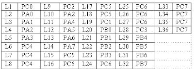
At the left corner of each road, a group of five LED’s (red, amber and 3 green) are arranged in the form of a T-section to control the traffic of that road. Each road is named North (N), South(S), East (E) and West (W). LED’s L1, L10, L19 & L28 (Red) are for the stop signal for the vehicles on the road N, S, W, & E respectively. L2, L11, L20 & L29 (Amber) indicates wait state for vehicles on the road N, S, W, & E respectively. L3, L4 & L5 (Green) are for left, strait and right turn for the vehicles on road S. similarly L12-L13-L14, L23-L22-L21 & L32-L31-L30 simulates same function for the roads E, N, W respectively. A total of 16 LED’s (2 Red & 2 Green at each road) are provided for pedestrian crossing. L7-L9.L16-L18, L25-L27 & L34-L36 (Green) when on allows pedestrians to cross and L6-L8, L15-L17, L24-L26 & L33-L35 (Red) when on alarms the pedestrians to wait.
To minimize the hardware pedestrian’s indicator LED’s (both red and green are connected to same port lines (PC4 to PC7) with red inverted. Red LED’s L10 & L28 are connected to port lines PC2 & PC3 while L1 & L19 are connected to lines PC0 & PC1 after inversion. All other LED’s (amber and green) are connected to port A & B.

WORKING:-
8255 is interfaced with 8086 in I/O mapped I/O and all ports are output ports. The basic operation of the interface is explained with the help of the enclosed program. The enclosed program assumes no entry of vehicles from North to West, from road East to South. At the beginning of the program all red LED’s are switch ON, and all other LED‘s are switched OFF. Amber LED is switched ON before switching over to proceed state from Halt state.
The sequence of traffic followed in the program is given below.
a) From road north to East
From road east to north
From road south to west
From road west to south
From road west to north
b) From road north to East
From road south to west
From road south to north
From road south to east
c) From road north to south
From road south to north
Pedestrian crossing at roads west & east
d) From road east to west
From road west to east
Pedestrian crossing at roads north & south

microprocessor traffic light control


ASSEMBLY LANGUAGE PROGRAMS:-
MODEL SMALL
.STACK 100
.DATA
CWR EQU 0FFC6 H
PORTA EQU 0FFC0 H
PORTB EQU 0FFC2 H
PORTC EQU 0FFC4 H
.CODE
START:
MOV AX,@DATA
MOV DS,AX
MOV AL,80H
MOV DX,CWR
OUT DX,AL
MOV AL,F3H
MOV DX,PORTC
OUT DX,AL
MOV AL,FFH
MOV DX,PORTA
OUT DX,AL
MOV AL,FFH
MOV DX,PORTB
OUT DX,AL
MOV CL,03H
CALL DELAY
TOP:
MOV AL,EEH
MOV DX,PORTA
OUT DX,AL
MOV AL,EEH
MOV DX,PORTB
OUT DX,AL
MOV CL,02H
CALL DELAY

MOV AL,FCH
MOV DX,PORTC
OUT DX,AL
MOV AL,7DH
MOV DX,PORTA
OUT DX,AL
MOV AL,57H
MOV DX,PORTB
OUT DX,AL
MOV CL,15H
CALL DELAY

MOV AL,E7H
MOV DX,PORTB
OUT DX,AL
MOV AL,FDH
MOV DX,PORTA
OUT DX,AL
MOV AL,EDH
MOV DX,PORTA
OUT DX,AL
MOV CL,02H
CALL DELAY

MOV AL,F7H
MOV DX,PORTB
OUT DX,AL
MOV AL,F0H
MOV DX,PORTC
OUT DX,AL
MOV AL,F1H
MOV DX,PORTA
OUT DX,AL
MOV CL,15H
CALL DELAY

MOV AL,FBH
MOV DX,PORTA
OUT DX,AL
MOV AL,FBH
MOV DX,PORTB
OUT DX,AL
MOV AL,50H
MOV DX,PORTC
OUT DX,AL
MOV CL,15H
CALL DELAY

MOV AL,FEH
MOV DX,PORTA
OUT DX,AL
MOV AL,FEH
MOV DX,PORTB
OUT DX,AL
MOV CL,03H
CALL DELAY

MOV AL,FFH
MOV DX,PORTA
OUT DX,AL
MOV AL,AFH
MOV DX,PORTC
OUT DX,AL
MOV AL,EEH
MOV DX,PORTA
OUT DX,AL
MOV AL,EEH
MOV DX,PORTB
OUT DX,AL
MOV CL,02H
CALL DELAY

MOV AL,BFH
MOV DX,PORTA
OUT DX,AL
MOV AL,BFH
MOV DX,PORTB
OUT DX,AL
MOV CL,15H
CALL DELAY
JMP TOP

DELAY:
MOV BX,10H
D1:
MOV CX,0FFFFH
D2:
LOOP D2
DEC BX
JNZ D1
INT 03H
END START


PROCEDURE:-
1. Connect power supply 5V & GND to both microprocessor trainer kit & Traffic light controller interfacing kit.
2. Connect data bus between microprocessor trainer kit & Traffic light controller interfacing kit.
3. Enter the program to control Traffic light.
4. Execute the program by typing GO E000:0B80 ENTER.
5. Observe the LED’s on traffic light controller PCB.

You might be also interested in:

:: MASM 611 SOFTWARE
:: bit reversal and sorting programs
:: Find Square Root of a hexadecimal number in assembly language
:: common intreview questions on 8086